Radiofax
Britain's Number Two Short Wave Station
1988-1992
RADIO ODDITIES
RADIOFAX
HOME PAGE
Radio Oddities.
Some curious or unusual radio events, by Trevor Brook
Spectrum Radio 558kHz Lots Road received without carrier Apparently unique, has anyone heard of freak through-a-hill propagation like this? One hot sunny late August afternoon during the exceptionally long dry summer of 1995 I was driving home and, probably uninterested in some package on BBC Radio 4's PM news programme, bashed through the AM memory presets on the (Philips DC777 shortwave) car radio. Spectrum Radio on 558kHz from Lots Road was appallingly distorted and quite unlistenable. This continued for several minutes until I reached home, where I switched on the communications receiver. 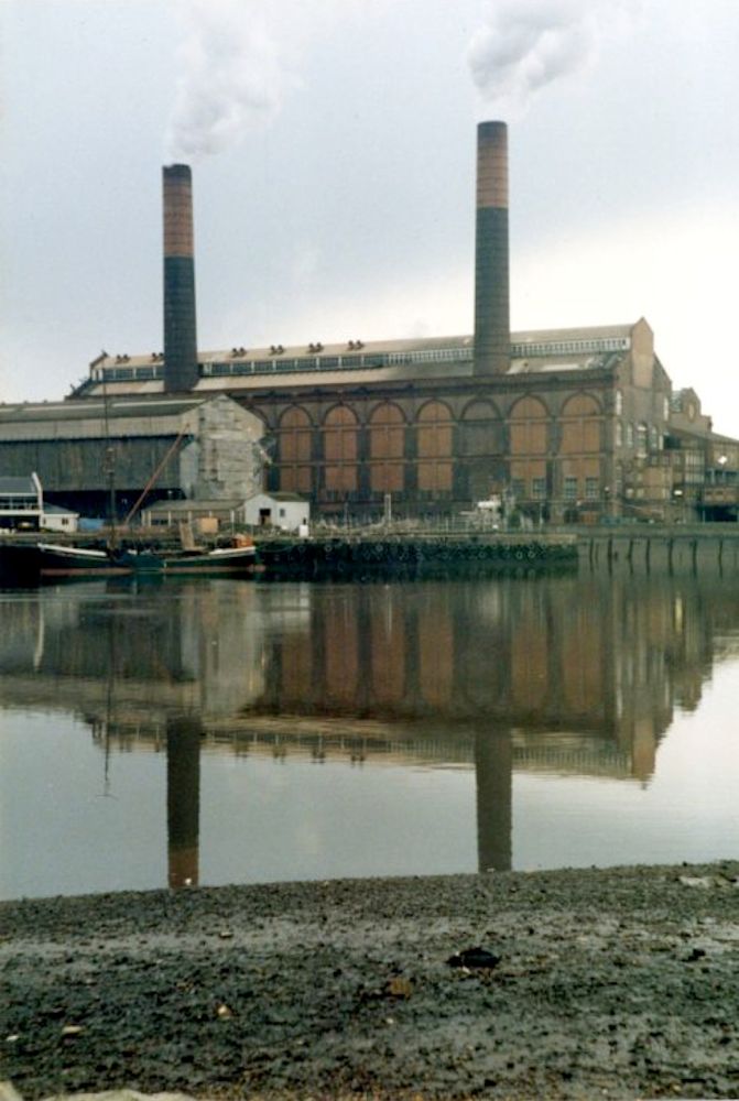
London Underground's Lots Road Power Station from across the Thames in 1977 At first, with the AM Synchronous Detector in use, the station sounded normal but the receiver's S meter was swinging around with the station's audio modulation. Switching to the envelope detector made the station grossly distorted, the same as on the car radio. 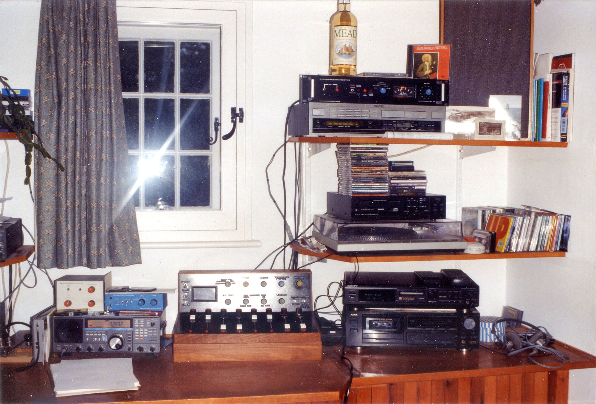
The active aerial and synchronous detector receiver at home A bit more investigation showed the upper and lower sidebands were similar and clean. There was simply a total lack of carrier, in other words, apparently perfect double sideband suppressed carrier. Knowing the transmitter design it seemed impossible it could be transmitted like this so there had to be some weird propagation cause. 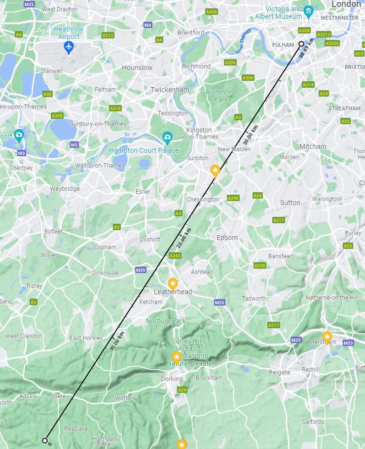
The signal path from Lots Road in the London basin to the Surrey Hills Might it be a clash between the usual groundwave over 38km and an unusual equal strength signal via the ionosphere with a path length difference which outphased at the carrier frequency? If this was some exceptional medium wave summer daytime near vertical incidence skywave (NVIS) reflection it would soon alter or cease altogether. 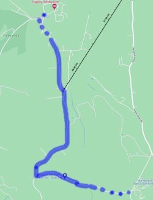
The road with nulling of 558kHz carrier and home, slightly off-centre to the angles affected The effect persisted though, and a drive the other way, northwards, showed that the distortion reduced at around half a mile and ceased even further along the road. Could there be two ground based paths for this signal? At VHF you'd be thinking of a second path reflecting off hills but this seemed implausible for medium wave. Anyway, if that was the cause the distortion would be constant. 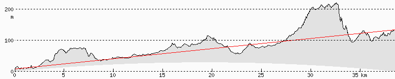
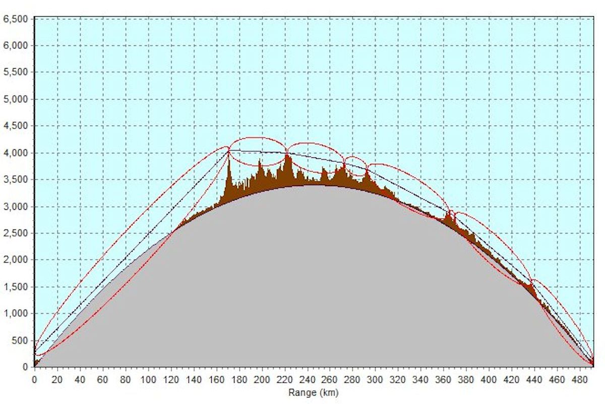
Path plot from Lots Road, beside the River Thames, via the 220m AOD North Downs to home, at 130m Groundwave signals follow the soil surface from the transmitter to the receiver. Seemingly the explanation for the carrier null is that the extended hot dry spell allowed a second and different length path to develop directly through the chalky North Downs. 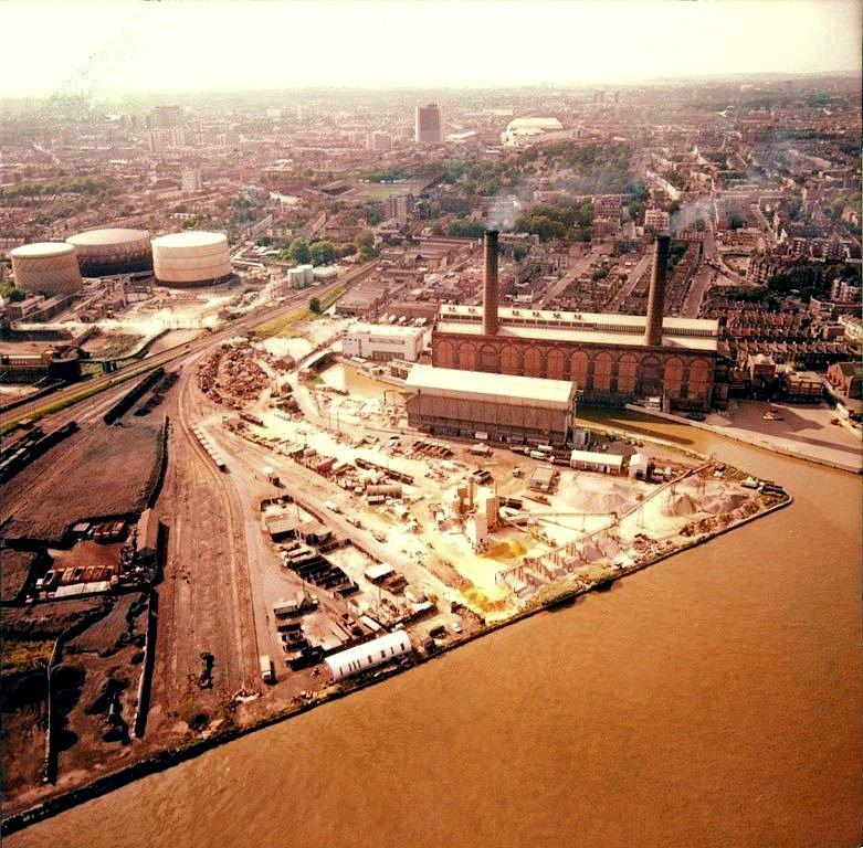
Lots Road Power Station between transmissions in 1979 558kHz is 537.6 metres wavelength, so cancellation needs a shorter or longer path through the hill of a half wave difference of 267.8 metres (or an odd multiple), with both having exactly the same path loss. A direct path through the hill, being less than 50m shorter, is insufficient, but the lower velocity factor of propagation through chalk makes the necessary delay plausible. It remains a remarkable fluke to have encountered such an event. 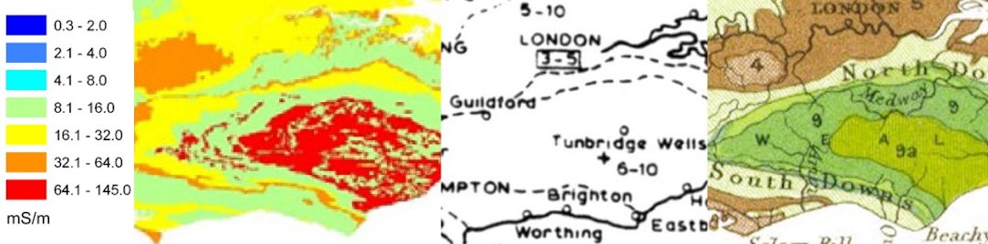
Three details of the London to South Coast area from: - Bedrock electrical conductivity map of the UK by David Beamish, 2013 - BBC conductivity map 1930, revised May 1951, showing mS/m - Stanford geological map Poor conductivity on both 2013 and BBC maps from geological map North Downs chalk Heavy rain two days later returned reception of Spectrum 558kHz to normal. Wetness improving the surface conductivity would reduce the penetration of radio signals into the hill, as well as aiding propagation of the usual groundwave over the hilltop at Netley Heath. Subsequent summers never recreated the extraordinary effect. In 2001 Spectrum Radio 558kHz moved from Lots Road to Crystal Palace, a less obstructed path. More details of: "the hottest two-month period in the entire CET series" and: "the driest in the 230-year EWP series" are in: The climate in the UK from November 1994 to October 1995 by Mike Hulme. 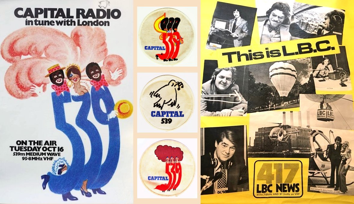
No expense spared - early publicity for Capital 539 and LBC 417 The original 1973 Capital Radio (557kHz/539m) and LBC (719kHz/417m) aerial at Lots Road was a double wire T aerial, suspended between straps around 3 metres below the tops of the two chimneys, each of which is 275 feet (84 metres) tall. The top hamper was 212 feet (64.6 metres) long with a double wire drop from its centre, tethered across from the south side of Chelsea Creek. The first coverage of Radio Clothesline and the 1973 Lots Road T aerial In Beatles photographer and photojournalist Frank Herrmann's apparently unique image of the T aerial, the picture editor had inked over the wires but missed the halyard on the west chimney. The track of it is just perceptible in the newspaper's halftone dots. The additional pair of wires to the east chimney is no part of the antenna but the steeplejack's ropeway, normally stowed out of sight. 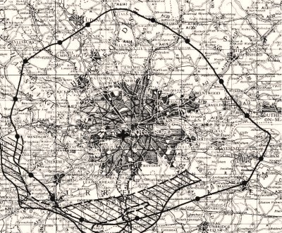
Along the Thames Estuary 557kHz field strength 3mV/m went 30% farther There were complaints about Ireland's RTE1 no longer being receivable in London and the installation was scornfully dubbed 'Radio Clothesline', though its coverage proved excellent. 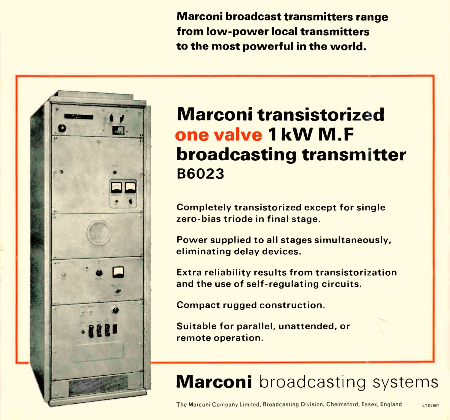
Marconi B6023 1kW AM transmitter The Independent Broadcast Authority (IBA) used Marconi 1kW transmitters, amusingly marketed "for the low-budget operator". These generated 25 Watts of AM from a transistorised series modulator which was then amplified by a linear valve PA, gobbling nearly 5kW of power. 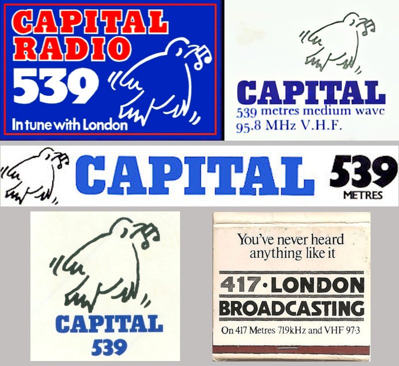
Lots Road 1973-1975: Capital Radio 539 and a pack of LBC 417 matches Planning permission problems for what became the IBA's Saffron Green site in March 1975, beside the A1 and 8.5km south west of Brookmans Park, had led to the temporary use of Lots Road. 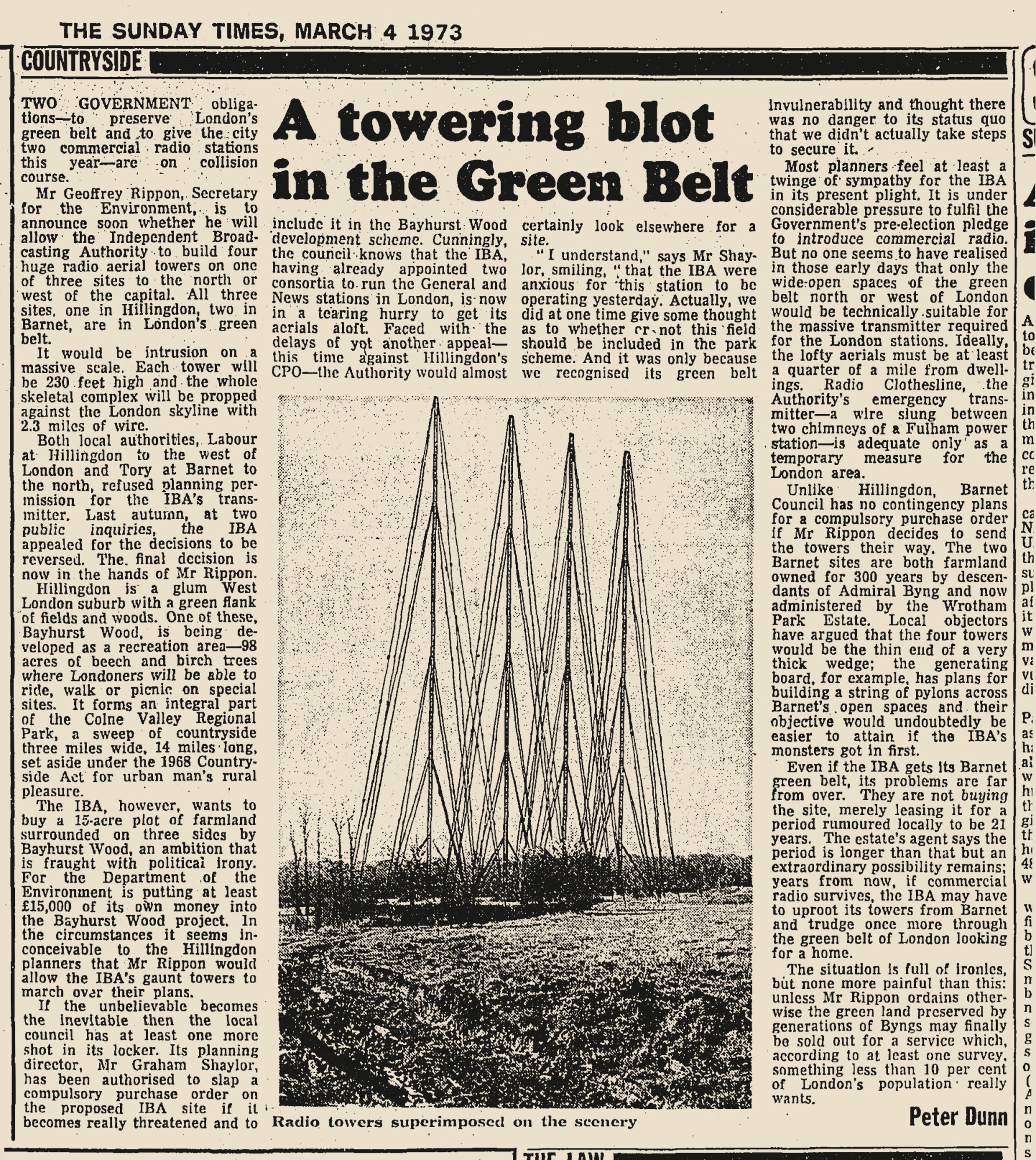
An alarming illustration of the proposed four mast directional array Despite Capital being impaired towards the east till Radio Veronica closed down on 31st August 1974, and with no other stations in the British Isles, daytime coverage of both Capital and LBC from Lots Road attracted listeners a hundred miles away. 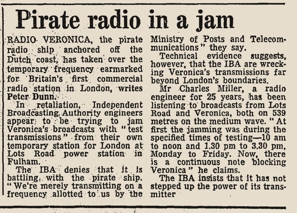
557kHz Radio Veronica moored off Scheveningen versus IBA Lots Road In March 1973 I chanced on hearing the first IBA test start, flattening Radio Veronica 557kHz off the Dutch coast which I'd had on while driving between Croydon and Bromley. 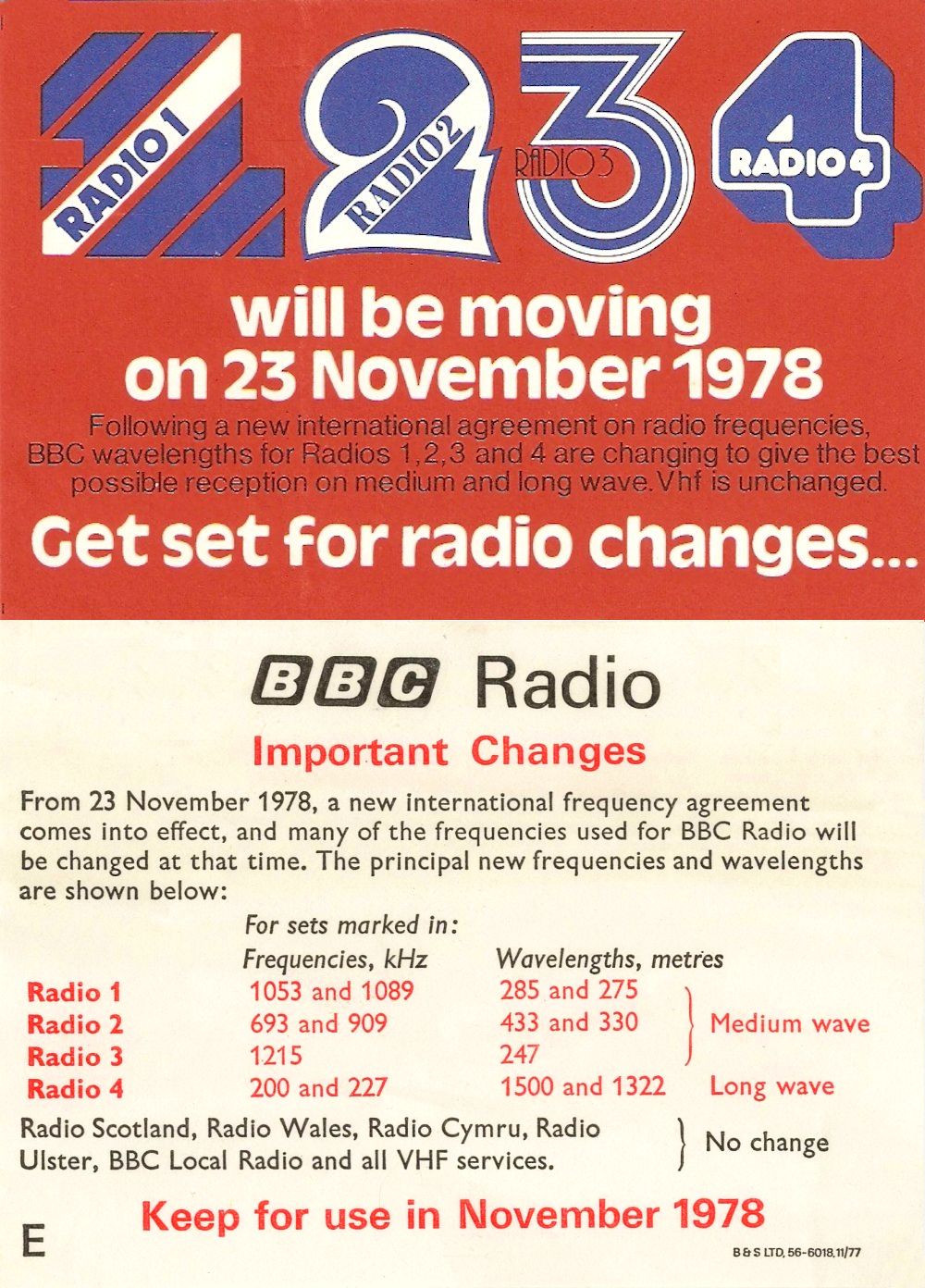
Medium Wave channels shuffled to multiples of 9kHz in the 1978 Wavelength Changes After Capital and LBC had moved to their permanent Saffron Green site in 1975, Lots Road next carried BBC Radio 4 720kHz, introduced in 1979 as a London filler following the November 1978 Wavelength Changes which had moved Radio 4 onto Long Wave, causing reception complaints. Wavelength changeover recordings. 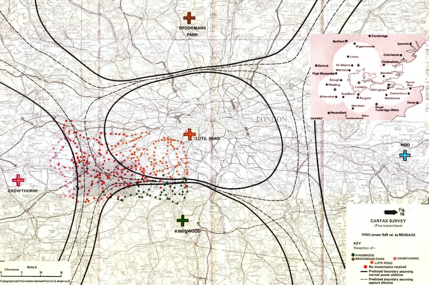
CARFAX trials on 526.5kHz from five sites, including Lots Road At the same time, following earlier tests at Brookmans Park and Tatsfield on 593kHz from March 1976, Lots Road also broadcast 526.5kHz between 1979 and 1981 for BBC CARFAX traffic information experiments, along with four surrounding 500 Watt transmitters, each adjusted to radiate 50 Watts EMRP: West, at Transport and Road Research Laboratories Crowthorne; North, initially on the north Tee antenna and then on one of the 1929 original 200 foot towers at BBC Brookmans Park; East, diplexed with BBC Radio Medway 1034kHz at Hoo and South, from a tall umbrella aerial covering most of the front lawn at BBC Research Department Kingswood Warren. Photo and coverage in Wireless World. In this early cellular lattice concept, with all transmitters on during signalling, the FM capture effect allowed phase modulated tones to unmute a car radio for AM messages relevant only to its location. CARFAX recording. Home Office frequency allocation antagonism and development of the radio data system (RDS) for FM, with its traffic announcement (TA) flag, sounded the death knell for the CARFAX project. 
CARFAX abandoned with chimney work ending the Lots Road T aerial era Passing Lots Road frequently, I watched the T aerial being cleared for chimney maintenance and rebuilding work. CARFAX trials from the site were abandoned and a lesser sloper aerial rising up to the east chimney alone, from the north bank of Chelsea Creek to the east, became the norm for BBC Radio 4 720kHz and the later 1990 Spectrum Radio 558kHz service. 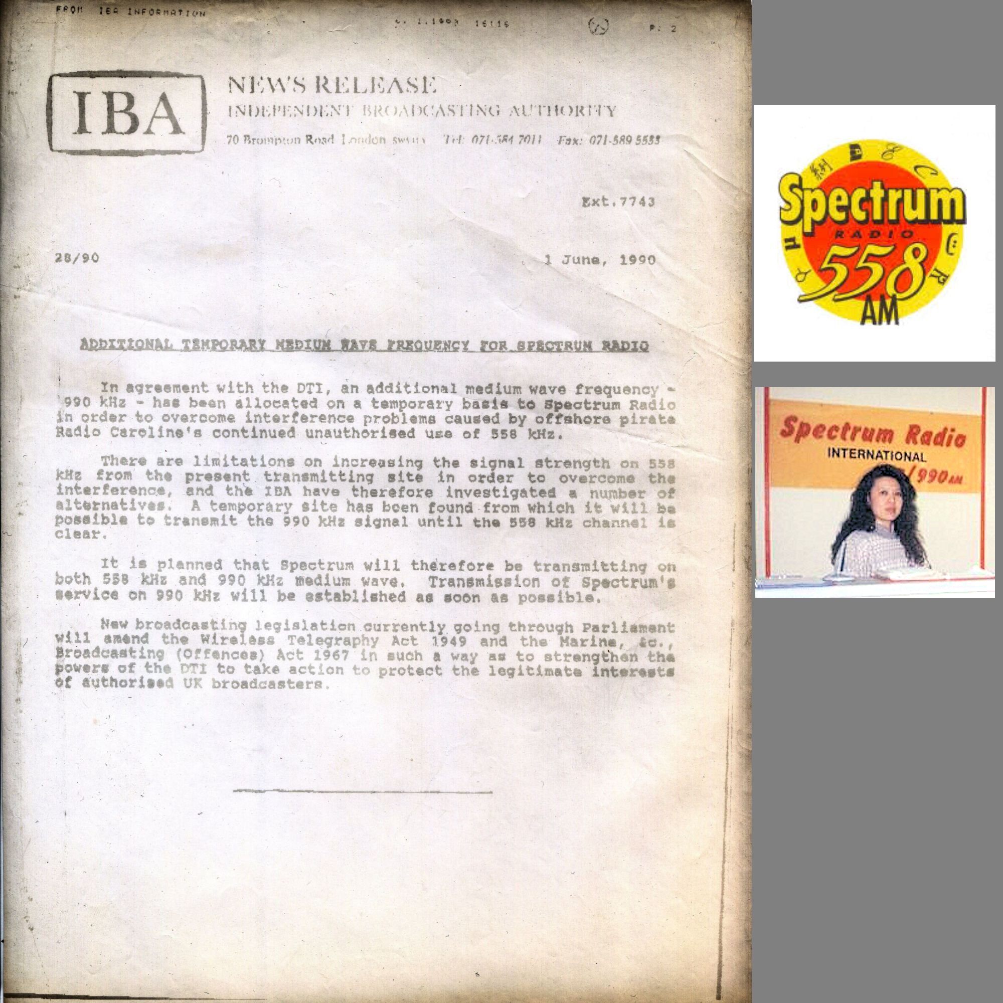
IBA press release fax: Spectrum Radio 558 and 990kHz simulcast In 1990, with 558kHz by then in use by Radio Caroline the inevitably poor service area of Lots Road, despite combining extra transmitters, led to the IBA adding a simulcast for Spectrum Radio on 990kHz from an aerial suspended between lighting towers at the Craven Cottage football ground beside the River Thames in Fulham. A single copper grounding strap was cleated across the towpath and routed down the embankment wall into the riverbed mud. 990kHz continued until 31st March 1991. Doubtless such a site would have been prohibited under post-Millennial RF exposure regulations. 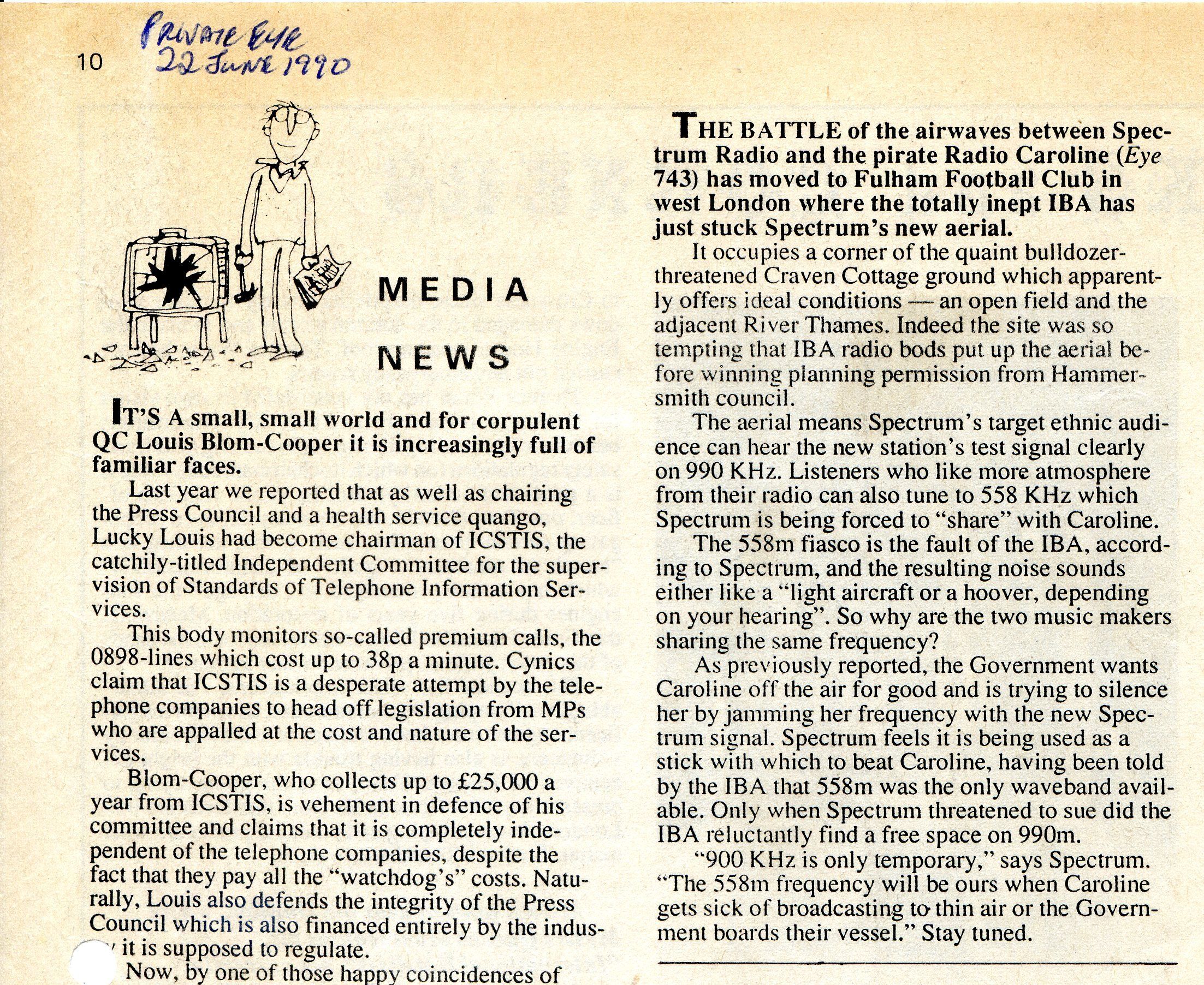
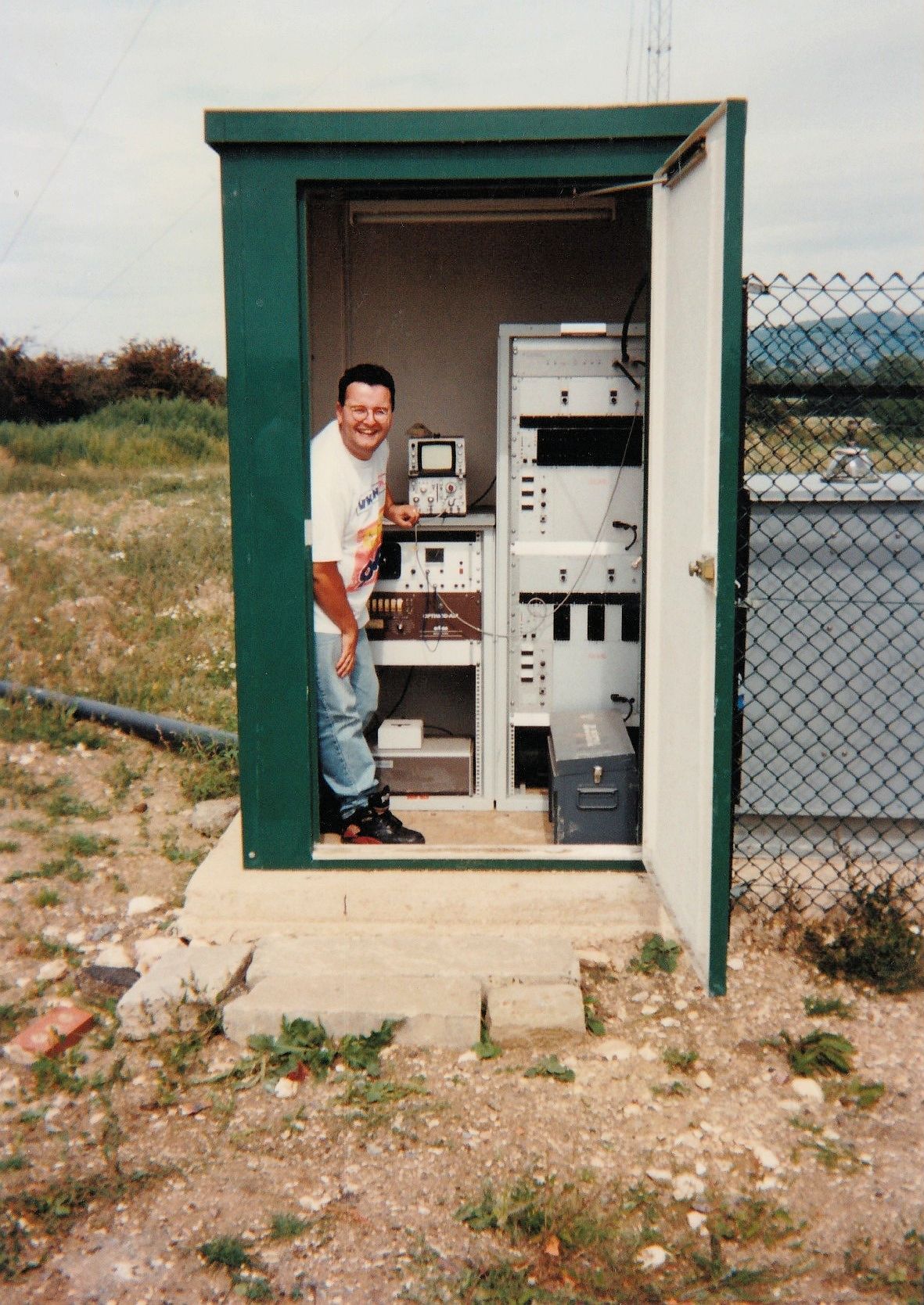
More atmosphere from your radio - Private Eye on the 558kHz fiasco In May 1990 I had written to IBA Director of Engineering Dr John Forrest about the inept allocation of 558kHz, the availability of other frequencies in London for Spectrum Radio and how IBA compliance with the DTI's Radio Caroline jamming scheme brought the engineering profession into disrepute. The IBA strategically 'lost' the letter, only replying after a reminder months later once transmission was under way (PDF). 2,500 field strength readings at the Forge in Cranleigh between 1984 and 2002 record licensed groundwave signals, including Spectrum Fulham 990kHz, Airport Information Radio 1584kHz, Care Brooklands 1278kHz, Radio London Frinton 1134kHz and Susy 531kHz as well as Caroline 558/819/963kHz, Laser 558/576kHz, Jackie 1323/1332kHz, Jennifer 819kHz, Skyline 1413kHz, London Greek 1125/1620kHz, Edge 738kHz and other pirates: transcribed to Excel. 12MHz broadcast AM arrived at receiver as single sideband While Radiofax was on the air, 625km away, it was the habit at The Forge to flip regularly through its frequencies. Excepting for Dellinger shortwave fadeouts, the 3MHz and 6MHz were always audible and a weak carrier by groundwave was detectable from the 12MHz service. Sometimes, when the maximum usable frequency (MUF) was high, 12MHz would appear strongly by sporadic E short skip. 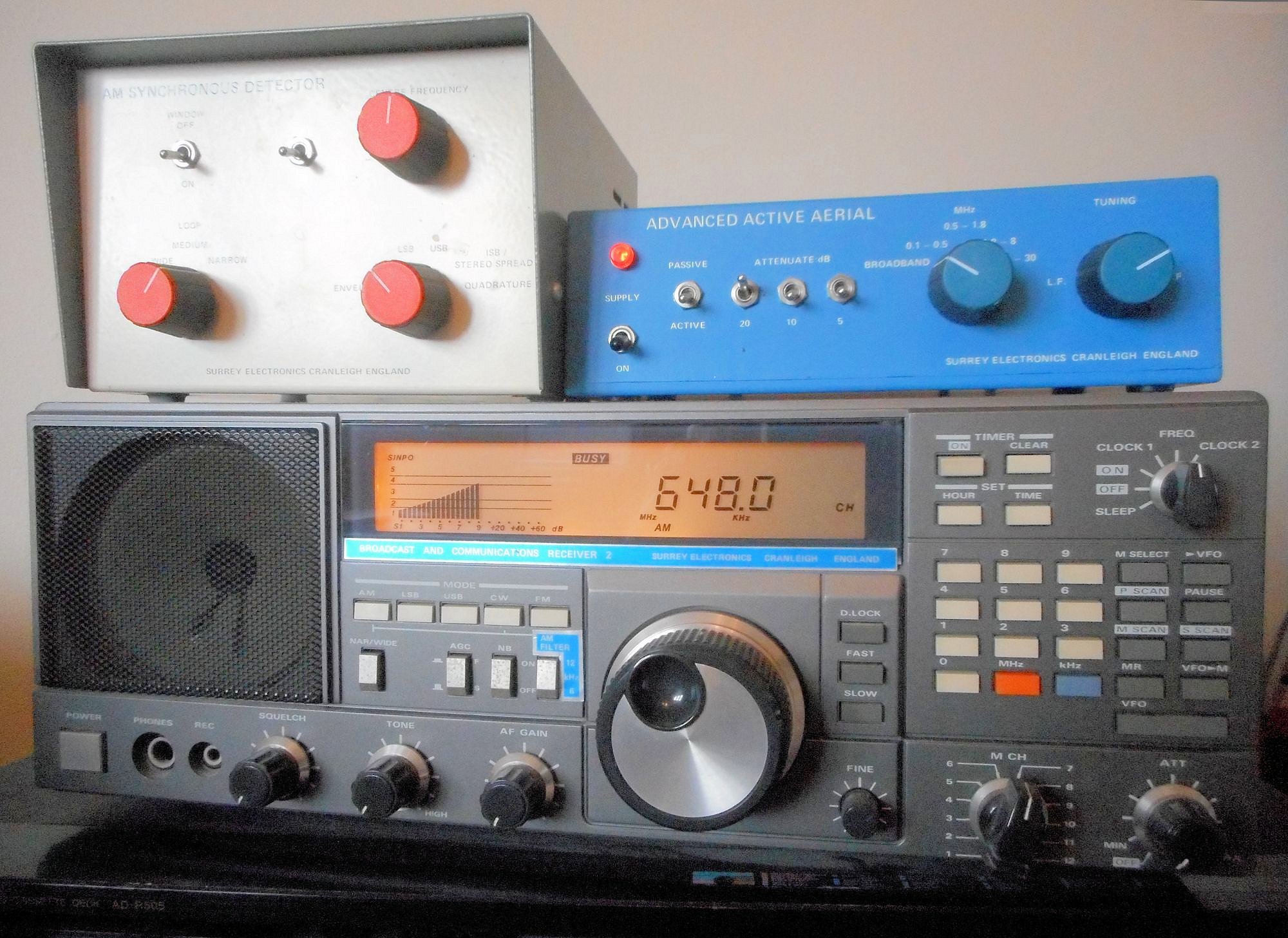
The receiving system One morning, there was a good signal on 12,255kHz but, just this once it was single sideband, LSB only. The transmitter of course could not produce this, we had chanced upon the MUF sitting precisely on the carrier frequency, the ionosphere reflecting the lower sideband but not the upper one. 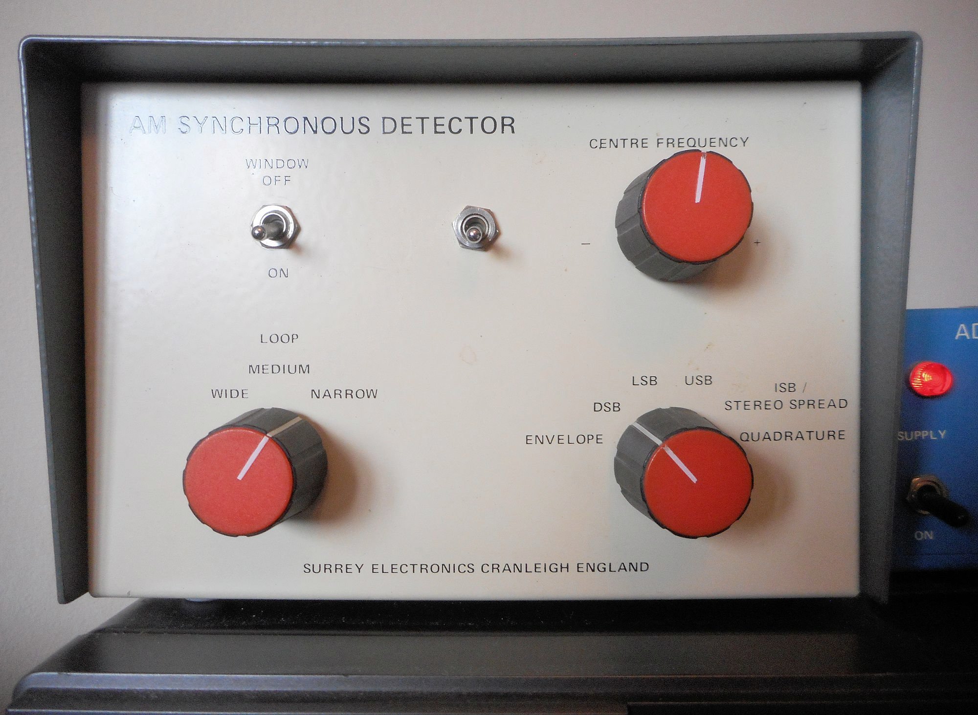
One switch swipes through Envelope, DSB, LSB, USB, ISB and Quadrature The situation persisted for about a minute and a half until the MUF suddenly moved on upwards, 'switching on' the upper sideband as well. It had been fascinating to see how abrupt the MUF cut-off was, leaving the upper sideband attenuated by more than 20dB. 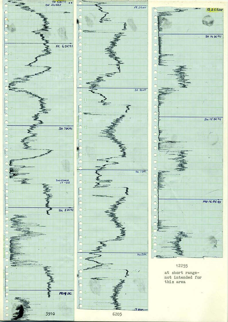
Chart recordings of the three frequencies in Surrey The main short wave receiving aerial at The Forge was a horizontal triangular loop between poles at each end of The Forge and in a small oak tree beside the stream across the yard. A balanced twin wire feeder dropped down into the building. From a south east sloping mountainside at An Cheathrú Trasna/Carrowtrasna in Inishowen East, Co. Donegal, 3910kHz was transmitted for night time, 5PM to 2AM, from a full wave dipole with an open wire feeder, 6205kHz had a colinear of three dipoles while 12,255kHz fed a vertical dipole with triple reflectors aiming south east, passing over the Foyle and audible by groundwave almost into Belfast. 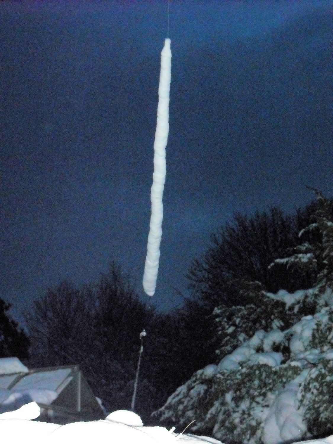
Adjusting a 12MHz reflector in the Surrey Hills - Donegal is never that cold Balanced feeds had baluns and the aerials, made with 14 SWG (2mm) hard drawn copper wire, had no breakages at the exposed site. Both 6205 and 12,255 were 24 hour services. Kilkeel 405 line TV sound offset as a propagation beacon... and remote weather station In the days before many amateur radio beacons, the Band I transmitters of BBC1 were useful indicators of VHF propagation conditions. Vision carriers employed slight frequency offsets, chosen as fractions of the 10.125kHz line frequency, which reduced patterning interference on the picture when there was a lift in conditions. A description of UHF video offsets is at 2 minutes in: IBA Engineering Announcements - 12 May 1987. 405 line AM sound carriers similarly employed offsets, chosen to avoid tones or whistles during lift conditions. 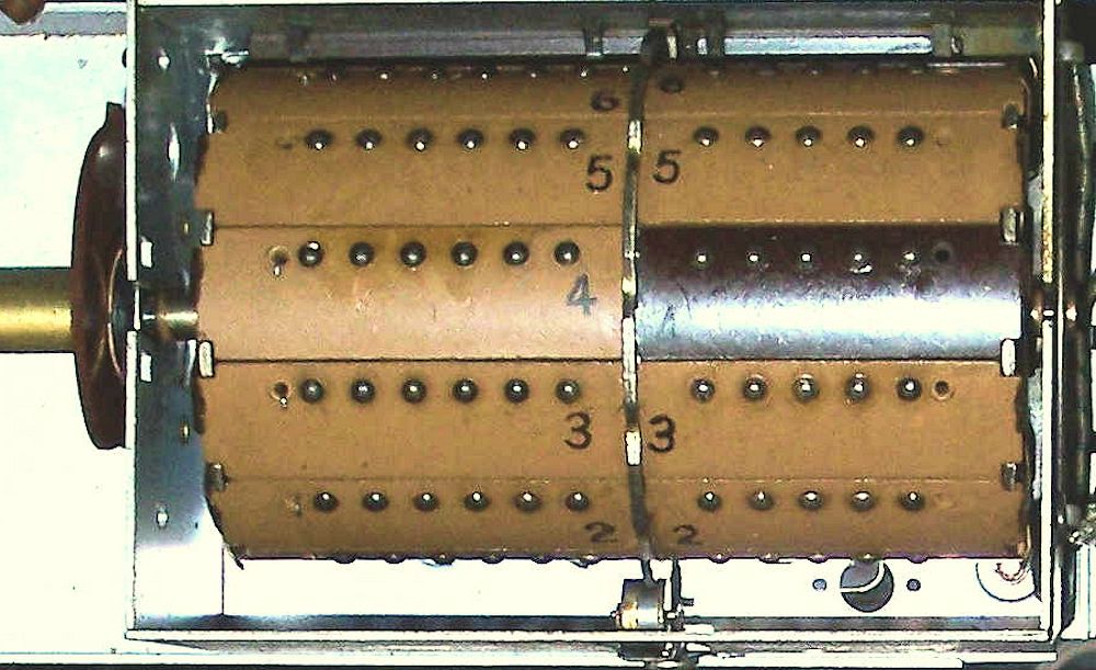
TV turret tuner RF and oscillator bakelite segments for each channel TV sets had turret tuners and free running oscillators with automatic frequency control (AFC) using the 3.5MHz higher vision carrier, while their 38.15MHz sound IFs had passbands around 50kHz wide. 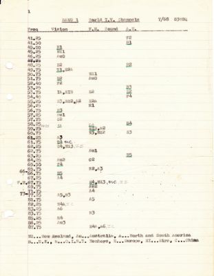
BBC 405 line and worldwide 525, 625 and 819 line Band I allocations The unique frequency of each transmitter on the same channel meant that a selective receiver could monitor the signal from a particular transmitter. Meldrum in the north east of Scotland on Channel 4, 58.25MHz, at 700km was an excellent indicator of north south conditions to be expected on the nearby 70MHz amateur band. Tropospheric propagation was always present, with the bonus of meteor scatter, aurora and an occasional rare Es backscatter. 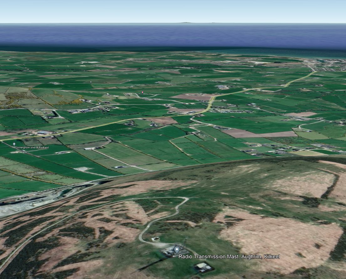
The Kilkeel hilltop site looking over the Irish Sea to Snowdon Towards the north west from Surrey, at 493km and also conveniently horizontally polarised, was the Kilkeel low power repeater in Co. Down, Northern Ireland, on Channel 3, 53.25MHz. 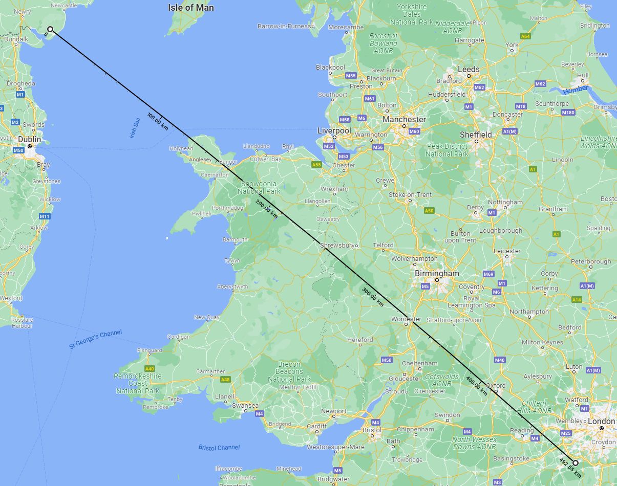
Line of sight to Snowdon, Kilkeel points towards its town and the sea With vision at 6 Watts on its southeast bearing (PDF), the sound carrier had an ERP of just 1.5 Watts, yet its carrier was always receivable, presumably aided by knife edge diffraction over an unusual path passing over 1,085 m (3,560 ft) high Snowdon/Yr Wyddfa, which is line of sight to Kilkeel. 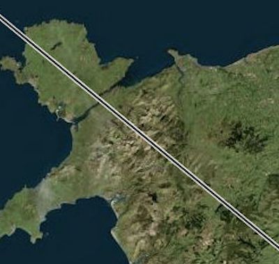
The path and its Fresnel zones, from Kilkeel to Surrey over Snowdon Separating the Kilkeel carrier using an offset of +37.125kHz from others on the channel using different offsets required a narrow filter, in my case a single 455kHz crystal filter in a much rebuilt Hallicrafters valve receiver. 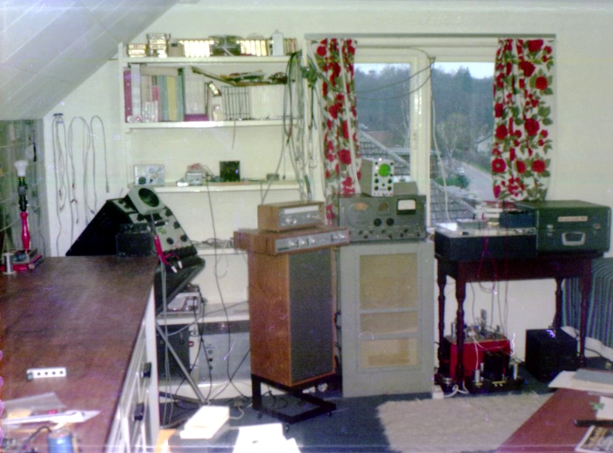
Hallicrafters communications receiver with Heathkit OS1 oscilloscope on top monitoring AM envelopes An ink pen chart recorder driven from the receiver's AGC system allowed long term plots of signal strength. The Kilkeel transmitter was odd because its exact frequency wandered slightly up and down, in and out of the passband of my crystal filter, creating a regular pattern on the chart recorder. 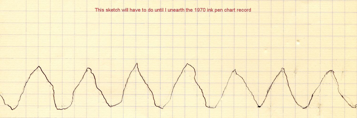
Regular strength changes on the chart caused by frequency drift, not fading The increase and decrease in frequency was caused by temperature cycling as the transmitter's crystal oven thermostat switched on and off. The switching period was related to the outdoor temperature at the Kilkeel site, amusingly giving an idea of the weather over there. 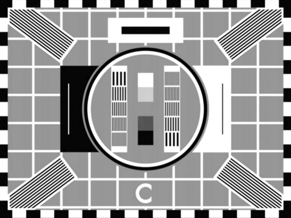
One variant of Test Card C Apart from some programmes for schools, transmitters were on the air during the daytime for the installation and repair trades, radiating Test Card C generated by photo etched Mullard monoscopes, along with 400Hz tone and copyright free music. More at The Test Card Circle. On walking through a front door of a house it was always obvious if a TV was turned on somewhere because of the 10.125kHz sound from its line output transformer and cathode ray tube scanning coils. TV line output stages, also generating EHT for the tube, ran around 40 Watts. If you were young, with hearing to 20kHz, after 1964 you could tell if the set was tuned to 625 line BBC2 with its higher 15.625kHz line frequency. 1960s RF heaters There was quite a craze for diathermy and RF heating in the 1960s. Diathermy treatment promised deep heat therapy for patients while RF heating was fashionably sold industrially for several purposes, plastic welding amongst them. Without any harmonic filtering and little screening these devices had stunning coverage, radiating for dozens of miles. 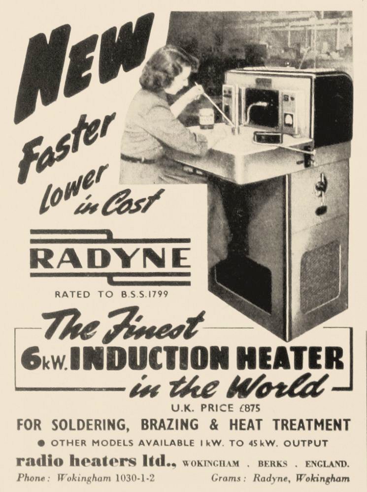
British RF Induction Heaters - up to 45kW The 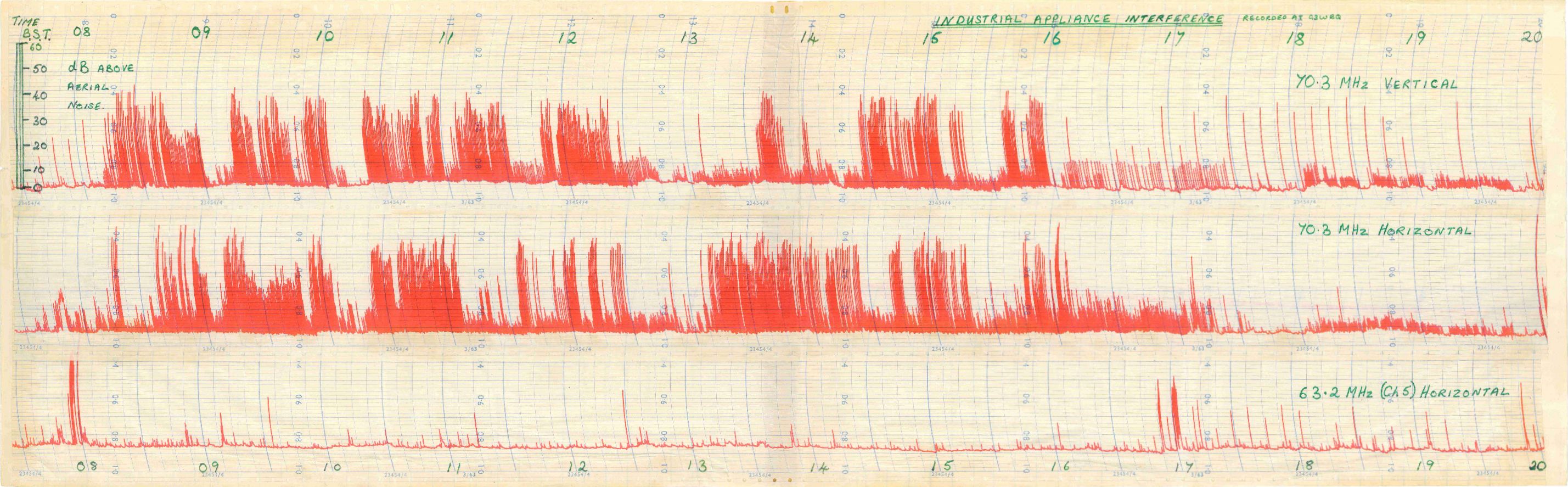
Chart recording of wipeout interference as an RF heater sweeps through 70MHz during the working day At least adjusted to avoid the TV broadcast band below 68MHz, my charts recorded on three successive days show one or more heaters operating throughout the working day. Every few seconds, on an affected channel, a cluster of unstable buzzy carriers would pass through from the heater, both AM and FM modulated by mains hum, sweeping across a couple of megahertz or so. With a 70MHz RF heater twenty miles away and side on, G3TCT beaming north from Guildford recorded G3RLE's Morse via auroral reflection in 1968, with interference every seven seconds: audio. 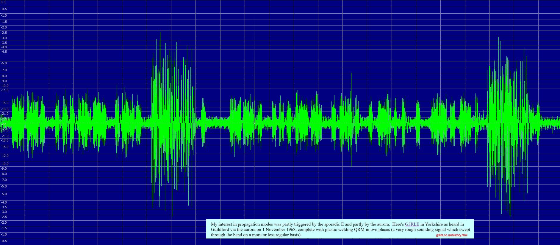
70MHz auroral Morse in 1968 with frequent RF heater interference Naturally, frequency varied with the load and temperature, so whatever industrial, scientific and medical (ISM) allocation was intended, 27.12 and 40.68 MHz being possible candidates, was purely notional. Better and more efficient techniques appeared and as these devices aged and needed maintenance their usage tailed off and the nuisance abated, as did the perpetual ticking of unsuppressed car ignition systems. Receiving RNI's 100MHz FM in Surrey at 124km The offshore station Radio Northsea International was unusual in having an FM transmitter as well as being on Medium Wave and Short Waves. The ship had come over to the UK from the Netherlands. Its 102MHz FM service soon moved to 100MHz quaintly, to non-European ears, announced as Channel 43. The Rohde & Schwarz 1.2kW mono transmitter fed a stacked pair of vertically polarised dipoles, unlike all services in the UK at the time which radiated horizontal only. The FM aerials were mounted on a pole above the shorter foremast of the Mebo II, about 15 metres high and producing a near-omnidirectional ERP around 1.5kW. 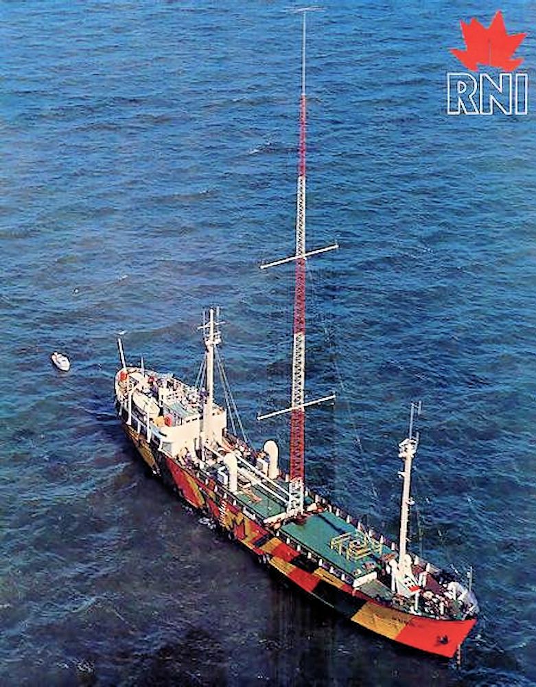
The RNI FM aerials are at the top of the Mebo II's foremast The radio spectrum in the UK was under the control of the Home Office. One of the officials' tactics to obstruct developments was to continue purchasing and installing radio telephone systems for the emergency services on post-war 96-108 MHz allocations within the Band II broadcast band, long after it was plain there was a demand for more broadcasting. So, with this mad situation, people with FM radios could additionally hear the police, fire brigade and gas board. To do so was of course illegal under the Wireless Telegraphy Act 1949 and the occasional person caught listening in did get prosecuted. In Britain, widespread piracy became the way other innovations, like baby alarms, garage door openers, Citizens Band Radio and cordless telephones, eventually became legal. 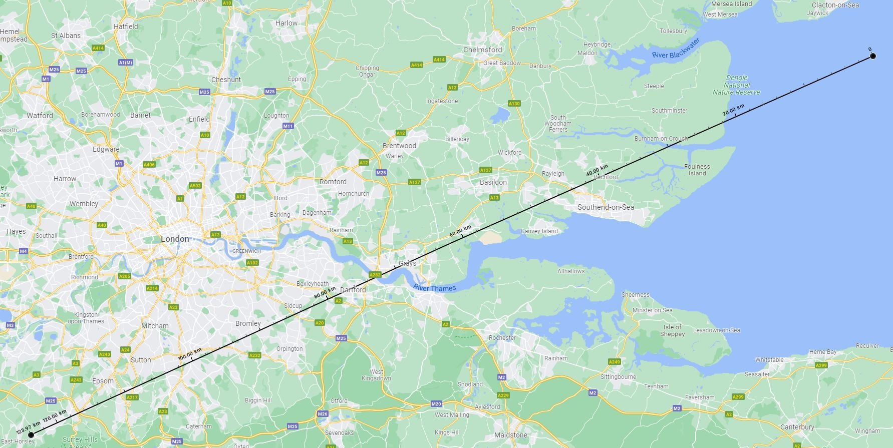
The path to Surrey from RNI's mooring 5 miles off Clacton People near the coast in Essex could hear RNI well on 100MHz, but would its signal make it as far away as 124km to Surrey? 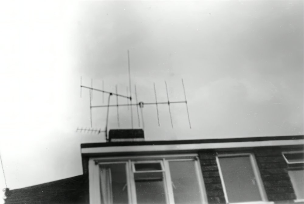
Summer 1970: Bands 1&3&UHF TV aerials with a vertical yagi for RNI FM The answer was yes, up to a point. I walked across the roof tiles to the chimney (don't try this at home) and twisted my J-Beam of Northampton 6 element yagi from horizontal to vertical. This made the signal listenable, though hissy. The listening experience was rather destroyed, however, by frequent radiotelephone chit chat from the public services operating between 99.9 and 100.1 MHz obliterating RNI's audio. How Kenny Everett and Russ Tollerfield created Radio London's Morse Code news sounder is at the end of: A 'stealing listeners' squabble between Guildford's County Sound 1476kHz and South Coast Ocean Sound 1170kHz Fixing Cheltenham Radio 603kHz which tripped off air during Drivetime Previously called CD 603, 603AM and Boss 603, in 1995 the Independent Local Radio (ILR) service for Cheltenham, running a 250 Watt transmitter for its 100 Watt Effective Monopole Radiated Power (EMRP) licence, had the commercially disastrous propensity to fall off the air during the busy listening time of 5 to 7 PM. 
The Cheltenham Radio 603 AM logo The transmitter would trip for two seconds and then reapply power. If three trips occurred within a short period it stayed off permanently until somebody drove up from the studios in Cheltenham, out to the site in a far flung corner of the racecourse which was once a rubbish tip, opened the cabin and pressed a reset button. 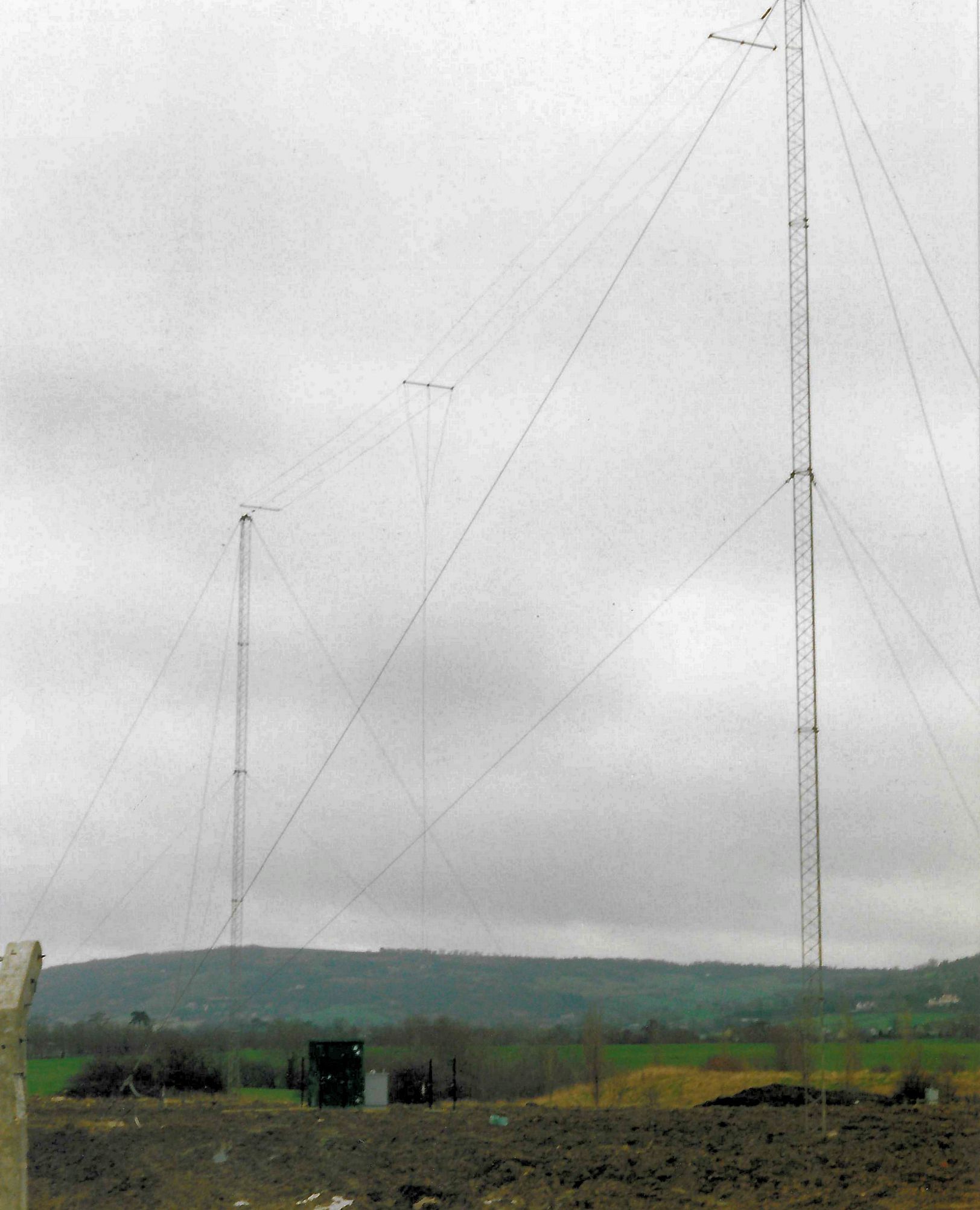
The T aerial favoured by starlings PHOTO: DAVE THORPE It seemed that large numbers of starlings congregating on the T aerial at dusk, before flying off to roost, were detuning the aerial sufficiently to upset the modern solid state transmitter. This power at Medium Wave is harmless to birds but if a bird has the sad misfortune to land on a high power Short Wave aerial the RF would blow off its legs. 
Cheltenham Radio station manager and breakfast presenter Marc Bond On auspicious days someone would be positioned at the site to scare birds. Station manager, Marc Bond, needed help. 
The half-metre tall eagle owl decoy To win a few weeks of time to devise a plan and obtain parts, my first action was to climb the east mast and install at the top a large decoy eagle owl I'd found in a field sports shop. 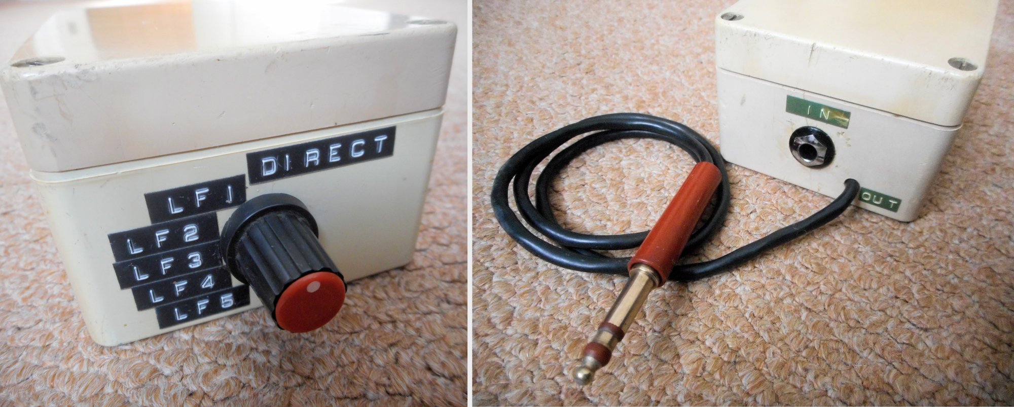
The hastily made balanced jack LF roll off box for the racks room Optimods don't really do low frequency roll-off, so in the studio racks room I also installed a balanced jack switch box which could insert various capacitors into the audio feed going out through the jackfield to the transmitter. The rotary switch, of course, was hermetically sealed with signal-grade gold plated contacts. 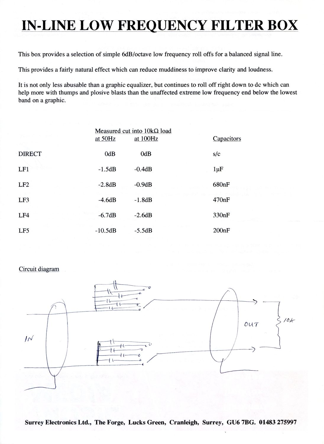
The balanced LF roll off switch box specifications Selecting an appropriate LF roll off crispened up the muddy sound of the station caused by losing treble due to poor return loss and sideband cutting in the narrowband transmitting aerial. 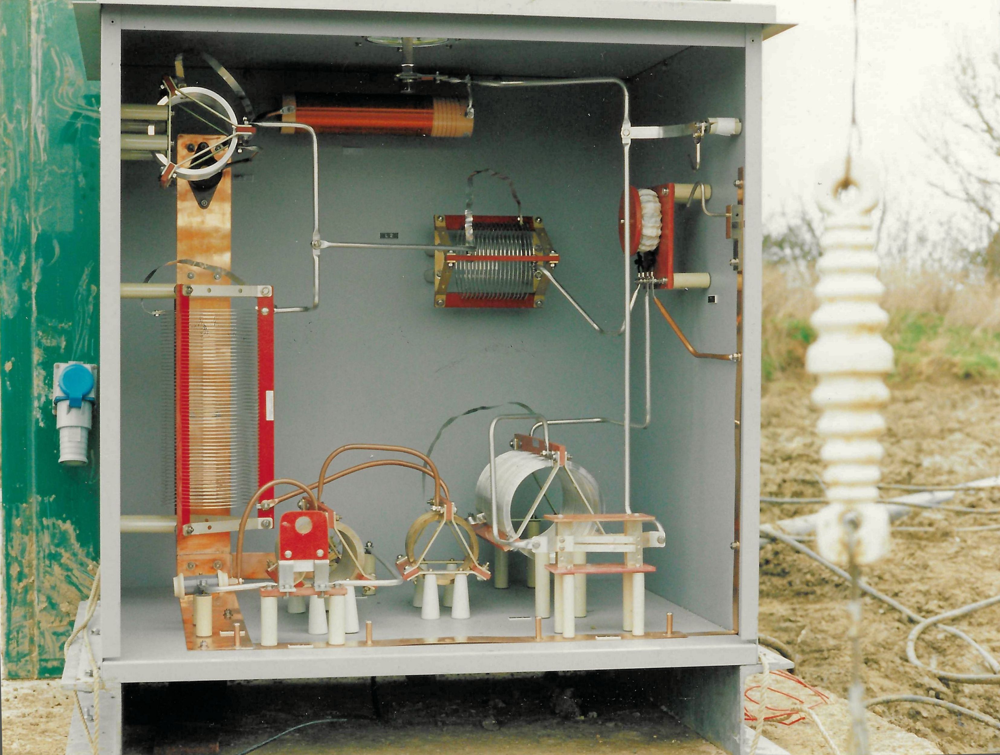
The original aerial matching system PHOTO: DAVE THORPE That night I took the station off the air at 1 AM to take antenna bandwidth measurements and examine the aerial matching unit properly. The aerial tuning hut was installed beside the centre of the T aerial drop, with the transmitter cabin directly beside it. There were a range of suspects, ranging from non-optimal to simply wrong:
Rik Scott frightens birds at the Cheltenham Radio 603 transmitter on Cheltenham Racecourse The main transmitter was a 250 Watt HCD Research Ltd. unit with a 125 Watt HCD as reserve. The manufacturer had no suggestions, so going through the circuit diagrams and output device specifications I devised circuitry changes to the transmitters aimed at making the installation more tolerant of reflected power, without risking damage. 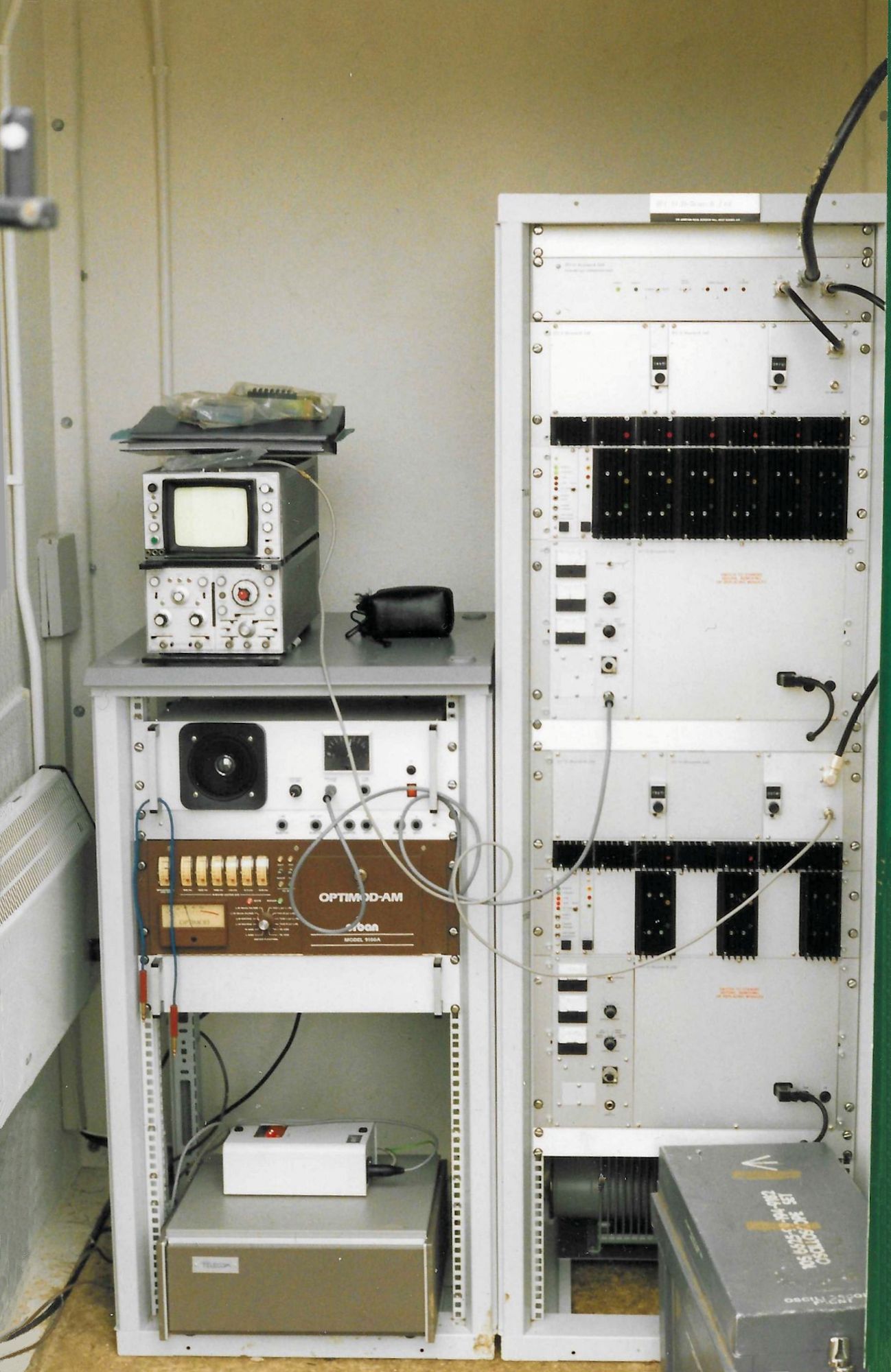
Main and reserve transmitters in the cabin PHOTO: DAVE THORPE After doing modifications on the standby transmitter and testing it into a dummy load it was put on the air while I modified the main 250 Watt unit, luckily with dry January weather while working on the ground at the cabin door. After an evening meal in Cheltenham I again took the service off the air at 1 AM and proceeded to dismantle the matching unit completely. I then rebuilt the match as an auto transformer. Providing no harmonic attenuation, it's a technique which normally comes into its own on Long Wave but it looked like a promising solution for this antenna, also dispensing with the need for a static leak. Each connection, including tap points on the silver plated coil, was made in the lowest resistance way possible. 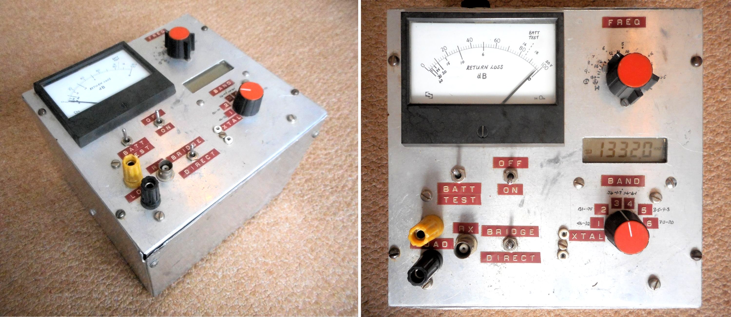
My special rechargeable return loss bridge, crystal tester and precision 100mW source covering 130kHz-20MHz Once I had the new arrangement matched to 50 Ohms at better than 30dB return loss on the 603kHz carrier frequency the moment of truth came by sweeping the return loss bridge up and down by 5 and then 10kHz. What a transformation in bandwidth! A mast stay could now be banged hard to shake the structure without any flicking of the return loss. The repowered transmitter with 100% tone modulation at 6kHz displayed only modest reflected power. Cheltenham Radio 603 now had proper treble with nicely symmetrical sidebands. 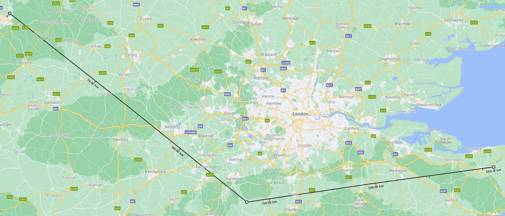
603kHz was shared with Invicta Radio in Kent, 116km. After the rebuild Cheltenham, 140km, became predominant in Surrey Apart from the jump in sound quality, it became obvious that the field strength was almost embarrassingly better. Confident that these measures were a permanent fix for birds, as well as ice, fog, wet soil or dry soil, back in Surrey, where Invicta Radio from Littlebourne in Kent had been the predominant signal on the channel, Cheltenham Radio was now the strongest. 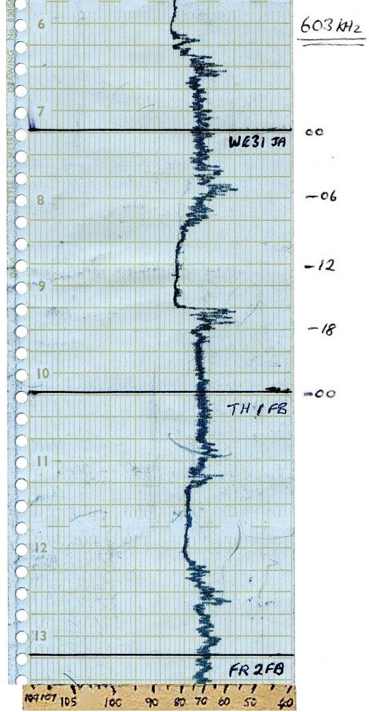
Foreign stations at night but a 3db increase in daytime signal on 1st February 1996 I had notified all the details of changes to the Radio Authority, as required by the licence. Perhaps recognizing that the site had always underperformed the power was never regulated downwards and so it continued until the station obtained one of those supposedly non-existent FM frequencies in 1998. 
Far out reception of 603kHz started after my 1996 enhancements Littlebourne was one of the sites where the IBA used aluminium, rather than copper, radial wires. It was unique in the UK for running 200 Watts by day and 400 Watts at night, leading to naughty station staff covering over the IBA's light sensor on the transmitter building. 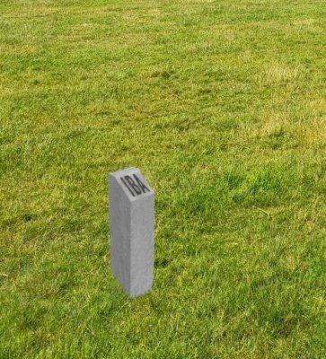
IBA Medium Wave aerial ground mat radial marker post On their early medium wave sites the IBA vaingloriously installed concrete marker posts around the field, with "IBA" moulded into their 45 degree sloping tops, delineating the extent of the aerial's earth mat radials. Though possibly deterring unthinking ploughing of the pasture, these were to prove convenient for copper thieves as well as being a hazard for grazing livestock. Quite shortly the markers were all cleared. Susy Radio 531kHz aerial visible from space - and a Long Wave test Around the millennium we heard of a pair of unwanted old Decca non directional beacon (NDB) transmitters. These were used for aeronautical beacons, periodically sending a callsign in Morse Code modulated carrier wave (MCW) and seeming to offer the prospect of use for SUssex and SurreY SUSY Radio's annual restricted service licence (RSL). We visited a delightful house in Bosham and returned with two transmitters and their four heavy linear power supplies. The Decca NDB transmitter in question It emerged that the transmitter generated a low level AM signal which was then amplified by six linear modules and combined at the output. The first 45 Volt power supply powered everything, until it was time to send the Morse Code when the output stages were switched up to 100 Volts, adding the 55 Volt power supply in series. This minimized heat dissipation while just sending carrier but allowed the four times higher peak envelope power needed on modulation... and also explained the peculiar 'crunch' noises beacons made just before and after sending their Morse! 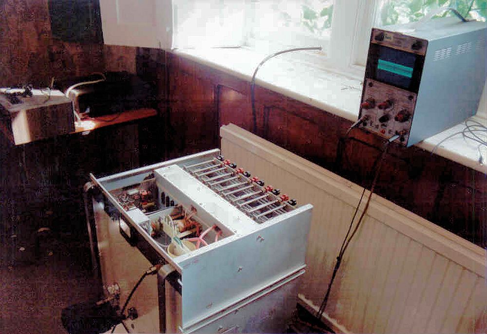
The 531kHz transmitter being set up After many modifications the units were producing 50 Watts of proper AM and the output, usually for the 350kHz region and involving ferrite and a variometer, would just tune up to 531kHz. 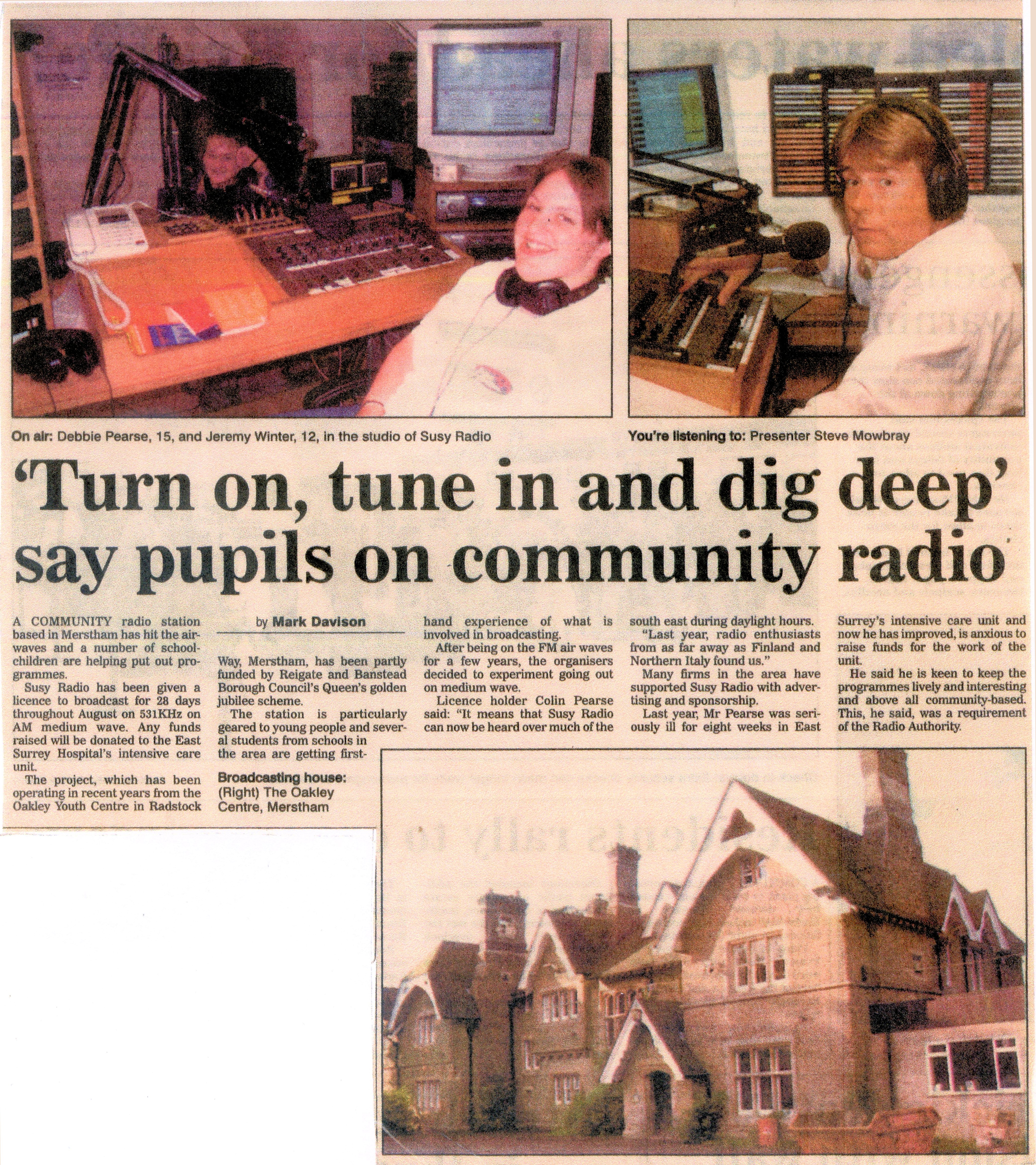
One newspaper's 2002 coverage of Susy Radio 531 Susy Radio's studio had fine trees in the grounds and a grassy area suitable for the aerial feedpoint some 70 metres from the transmitter room. In August 2001 a double riser and very long top hamper was installed in a figure 7 shape with an extensive ground system of long radials and concentric circles of copper earth rods. 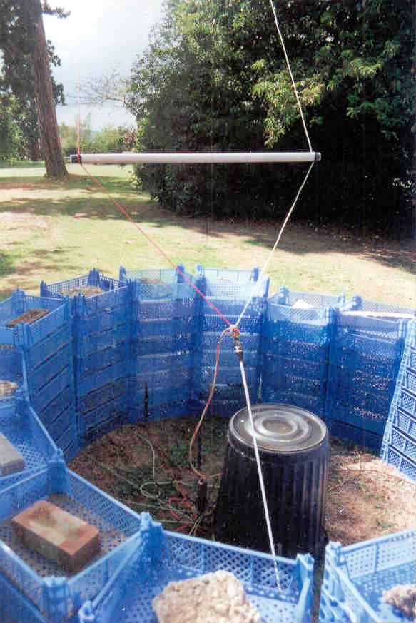
The first Susy Radio 531 aerial matching and feedpoint An L match to 50 Ohms produced return loss of 40dB at 531kHz and below 25dB +/-6kHz with the inband 1062kHz second harmonic hardly detectable beyond the driveway. 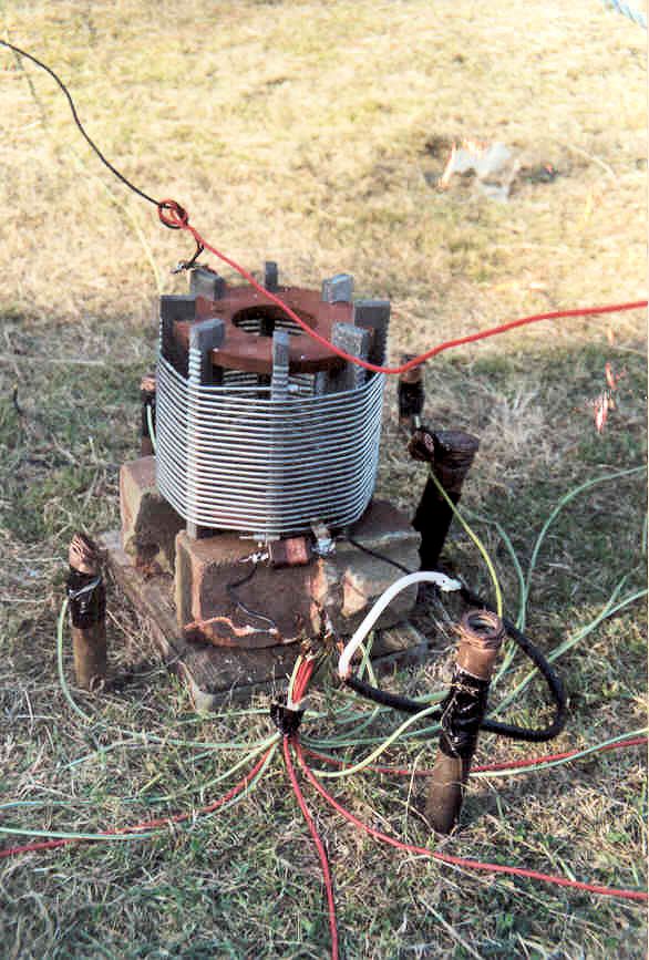
Quick check of a workable match at 531kHz For the following year's licence I raised the feedpoint into a tree. A hamper of wires, along with the coax, rose from the earth mat up to the tree with the aerial itself continuing on upwards. Elevated feed was a lot of bother for a possible 0.5dB improvement in signal. 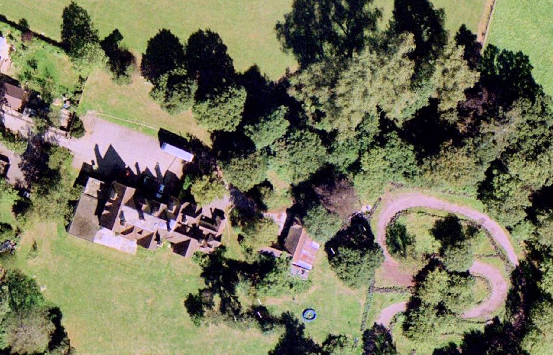
The protected feed point and white spacer bars of the riser and hamper show in 2001 satellite photographs Knowing that two wires withstood the weather, to reduce losses in subsequent years I used more wires in a wider spaced riser. Replacing the linear power supplies with switch mode units gave some improvement in efficiency. 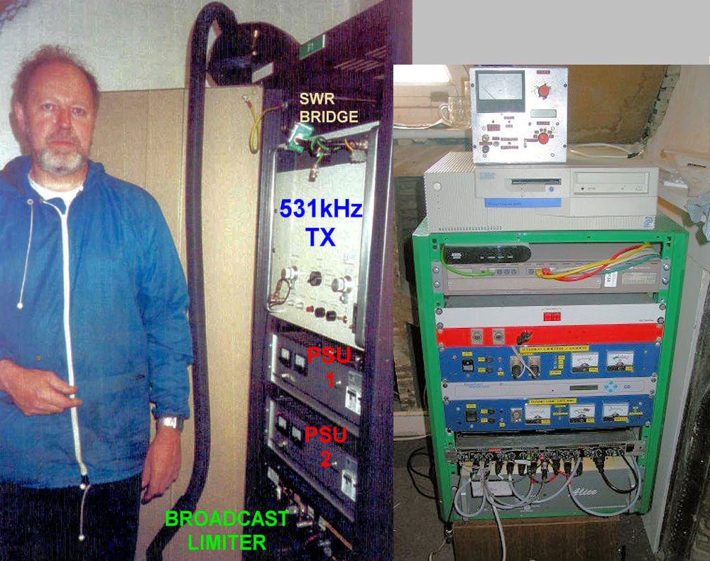
Amateur TV operator John Stockley G8MNY looking after things The Radio Authority had been reluctant to licence 531kHz, claiming it was impractical to provide a serviceable 1 Watt EMRP signal at such a low frequency. The opposite happened. Phone calls came from miles away and listeners were astonished at the coverage. 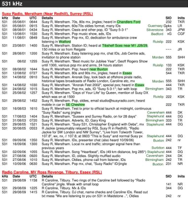
Reports directly to Susy 531 and BDXC reception reports, 2001 - 2006 As I'd hoped, many people happened upon Susy Radio as the 531 default button on car radios and jealousy even caused a complaint to the Radiocommunications Agency. 
Overseas reception confrmation card from Susy Radio 531 AM This 2006 recording of an 11AM Susy 531 news, with station identification by Dave Owen, is by Hugo Matten at 198km in Veurne, Belgium. 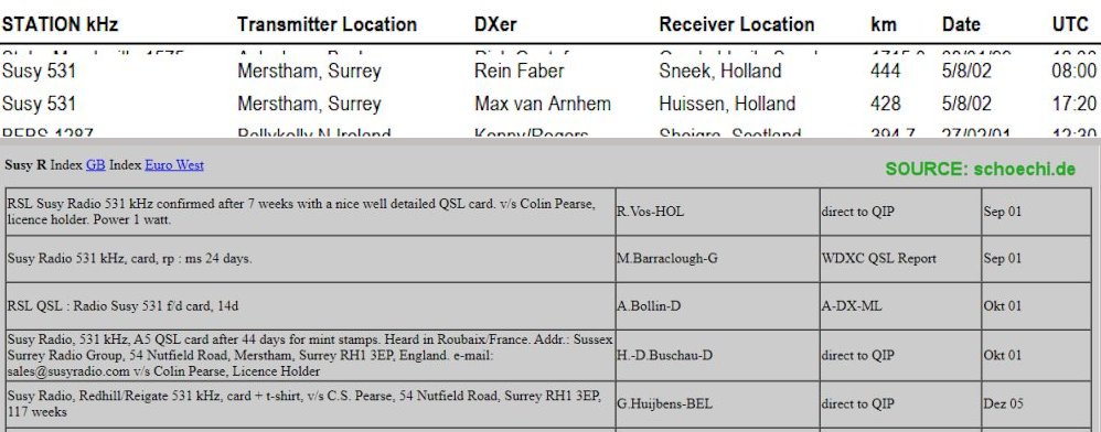
Netherlands in MWC's farthest RSLs, plus confirmed in Belgium and Germany In 2009 the idea was copied from the Ross Revenge in Tilbury by Radio Caroline, who have a geographically widely spread listener base. 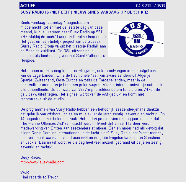
Susy 531 was detectable during the daytime in Belgium and the Netherlands A transmitter which had originally operated rather lower in frequency than 531kHz and an aerial which stood a chance of being matchable gave rise to the idea of a Long Wave trial. Using a precision signal generator to inject the required 1080kHz the transmitter would operate at the other extreme of its tuning, on 270kHz. Before dismantling the aerial for another year, one pleasant dry day an attempt was made to match the aerial to 50 Ohms using a box full of high voltage RF capacitors and a selection of large coils wired in series. As expected, return loss rose dreadfully on the sidebands (6.4kHz wide at 10dB return loss) but the horribly inefficient Class A output stage of the Decca was unlikely to care. So, an exciting tone was radiated. 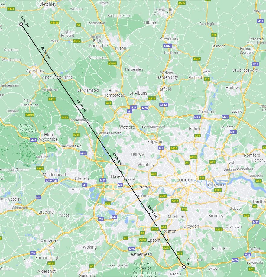
A 92km path over which 270kHz Long Wave was stronger than 531kHz Medium Wave From the few who knew of the experiment the furthest reception report came from 92km away to the north west where, as one would hope, 270kHz was subjectively a better signal than 531kHz on an Audi car radio. A less lossy match would need a proper large diameter coil with thicker conductors, though lower losses would come with the consequence of an an even tighter bandwidth. The already diminishing proportion of radios covering Long Wave meant there was little appeal in applying for the very first RSL licence on that band. A 'stealing listeners' squabble between Guildford's County Sound 1476kHz and South Coast Ocean Sound 1170kHz In late 1988, as Independent Local Radio (ILR) licencees were required to cease simulcasting and split AM from their FM services, the trend to Gold music services led to upset by the operator of County Sound. 
County Sound Gold in Surrey and north Hampshire with Ocean Sound to the south I was engaged by Ocean Sound's Chief Engineer Russ Tollerfield (onetime 1960s offshore Radio London engineer) to submit evidence, for a court case, that there was no incursion by Ocean Sound into County Sound's coverage. 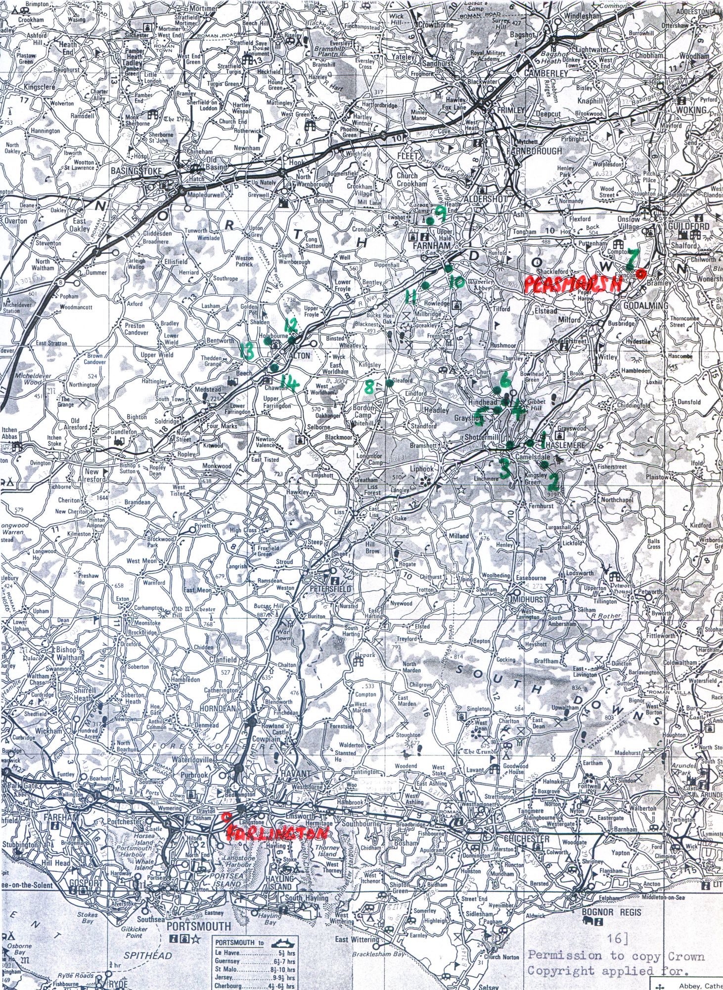
14 survey points chosen in the contended area The project involved checking relative field strengths of the two services at a number of survey points in populated areas towards the southern fringes of County Sound's measured coverage area (MCA). Essentially the issue was that by using the same 'Gold' imaging, Ocean Sound were potentially claiming listeners who 'should' be using County Sound. There were echoes of the High Court injunction just four years earlier by John Aumonier of Crawley's Radio Mercury against Radio Jackie on the other side of the North Downs. During that period I had been endorsing the back of every advertiser's cheque made out to Radio Jackie and paying them into one of my accounts. 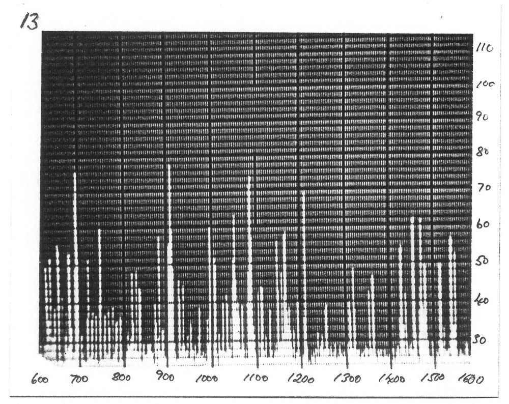
Mobile spectrum analyser display of signal strengths at a supposed boundary in the countryside Hundreds of field strength measurements were collated which showed there was no commercial competition by Ocean within County Sound's area. The entire report, which includes measurements of other AM services including Radio Caroline 558, is here. 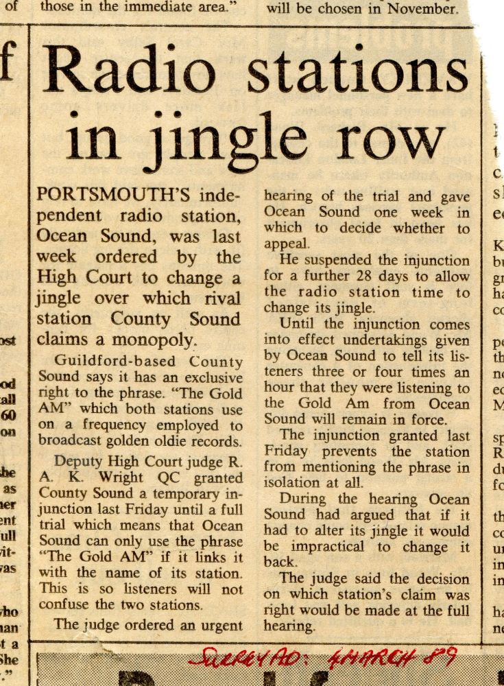
A newspaper report early in the court case Contrary to promises in Parliament and the localism requirements of the Sound Broadcasting Act 1972 which enabled ILR, over subsequent years almost all stations, including Ocean and County Sound, merged into national networks. Had there been effective listener groups might a judicial review have blocked this happening? Ironically, when the pirate ships closed in 1967, the public had really wanted similar pseudo-national stations but government was minded to allow only local services. 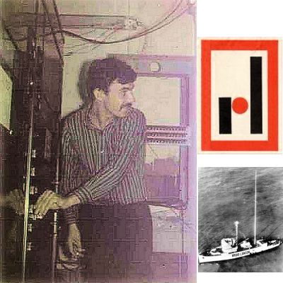
Russ Tollerfield does the final closedown of Radio London 266 PHOTO: DAVID HAWKINS After the BBC, Ocean's Chief Engineer Russ Tollerfield (1944 - 2017) had been engineering for Wonderful Radio London, Big-L, on the MV Galaxy, doing the very last transmitter switch off at 3pm on Monday 14th August 1967. 
Radio Victory: ILR contractor for Portsmouth, 1975 - 1986 Next he was Chief Engineer at Radio Victory in Portsmouth, which later lost its franchise to Ocean Sound. 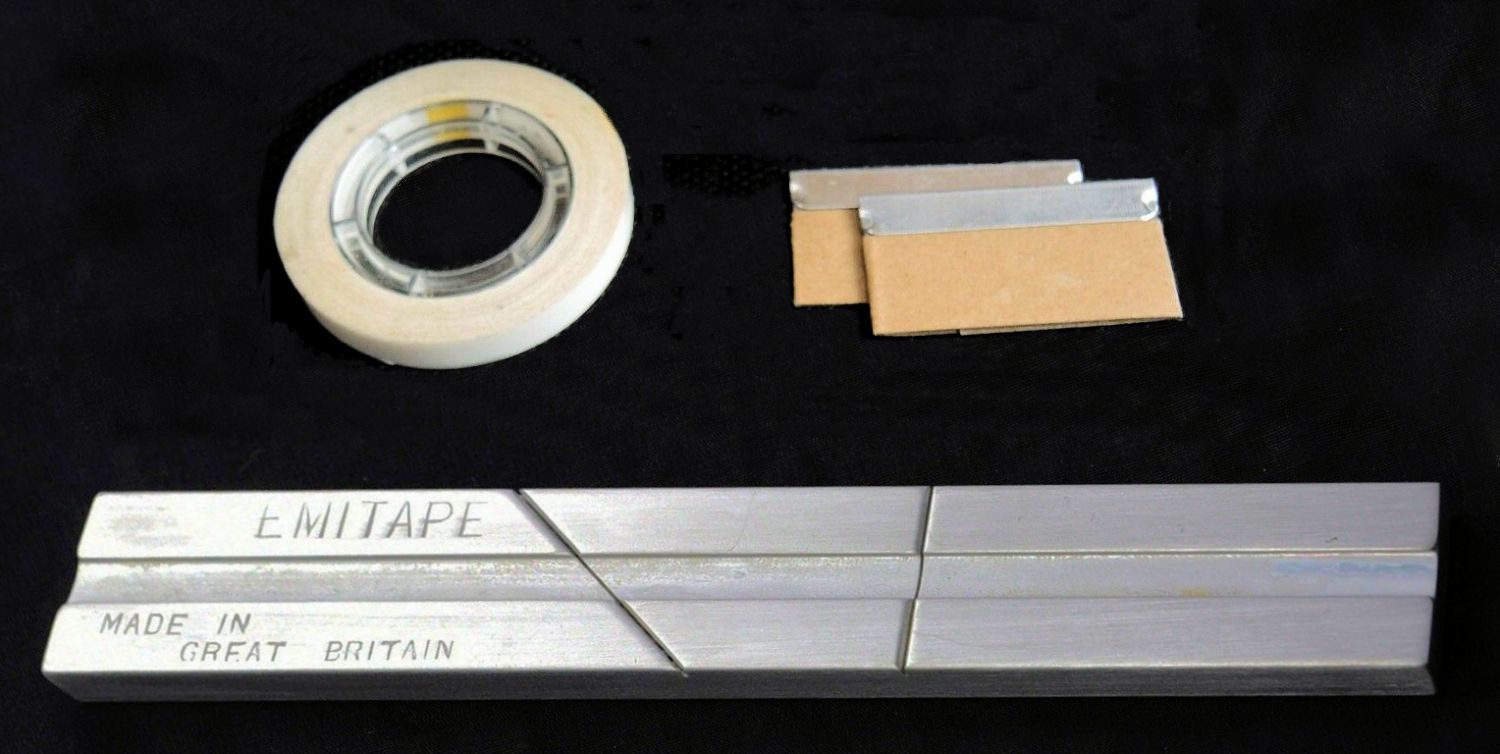
Jointing tape, single edge razor blades and EMI splicing block It was Russ, radio amateur G3SQD, who conceived of and spliced tape with Kenny Everett to create the original "R L" high speed Morse Code sounder preceding each Radio London news item. Seven pieces of tape and six pieces of leader were cut accurately to length and 14 splices made at 45 degree angles to create the proper fade-in fade-out keying characteristic. The result was then recorded onto a NAB cartridge so newsreaders could press the player's button to fire the sound. 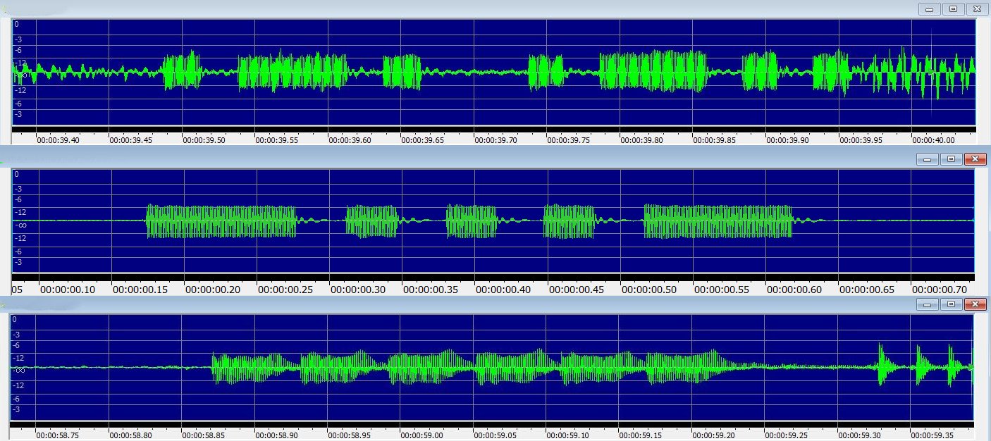
Original R L Morse news sounder / ▄▄▄ ▄ ▄ ▄ ▄▄▄ Morse August 1966-March 1967 / six pips March-August 1967 The Post Office amateur Morse test was at 12 words per minute (WPM). Initially, at the start of Radio London's news, Russ and Kenny's ▄ ▄▄▄ ▄ ▄ ▄▄▄ ▄ ▄ "R L" Morse sounder is heard with a 470Hz tone at 25 WPM, while for each subsequent story topic it is doubled in pitch, 940Hz, and speed to 50 WPM used for machine readers. A different Morse sounder, ▄▄▄ ▄ ▄ ▄ ▄▄▄ "BT", a symmetrical prosign meaning 'new message', at 1.2kHz and 35 WPM was used later. From March 1967, six very rapid 735Hz non-Morse pips were used. All the tone types were rich in harmonic content. This recording shows the four Radio London news sounder types in sequence: -- the ▄ ▄▄▄ ▄ ▄ ▄▄▄ ▄ ▄ "R L" Morse Code, slow then fast, on Saturday 21st August 1965, with Ed Stewart -- the ▄▄▄ ▄ ▄ ▄ ▄▄▄ "BT" new message prosign on Tuesday 27th December 1966, with Keith Skues (AUDIO: Alan Field) -- the six rapid pips on Sunday 6th August 1967, with Ian Damon. I believe this pacy - topic / sounder / story - idea was never really used again in British radio. Or was it? If you want to write ▄ ▄▄▄ ▄ ▄ ▄▄▄ ▄ ▄ Morse in HTML try code like this: <span style="font-family: monospace; font-size: 65%; vertical-align: 1.3ex; white-space: pre-wrap;"> ▄ ▄▄▄ ▄ ▄ ▄▄▄ ▄ ▄ </span>. The Ocean Sound story is described by Tony Harding in: Ocean Sound and Me. The night lightning struck an aerial running around my bed At midnight one night when I was 13 a deafening bang suddenly woke up the whole house. My sister's and my bedrooms were upstairs and I awoke to a fizzing sound with a discharge from along the edge of the window frame, seemingly going through the glass to outside and producing choking white fumes which rose up to the ceiling. 
Clear plastic covered aerial wire was vaporised and melted My conventional 132 foot (40 metre) longwire strung from an oak tree along the garden ran into the bedroom through a piece of plastic tubing in a hole I had drilled in the top left corner of the wooden window frame and all down its left hand side. It then trailed along the entire length of the bed, between the bed and the wall, turned the corner across the bedhead and up to a radio on my bedside chest of drawers. 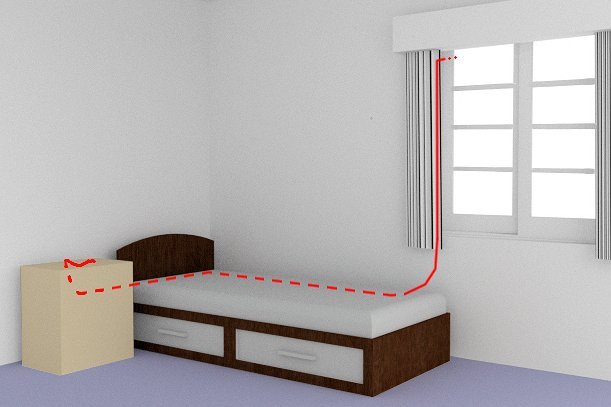
Aerial down the window, alongside the bed, across the bedhead and to the radio In daylight next morning the support halyard with its white porcelain egg insulator dangled uselessly from the tree. There was no aerial but a decorative trail of small shiny drops of solidified copper ran in a straight line across the lawn. There were no signs of damage to either the house or the oak tree itself. Unsurprisingly, the home built transistor medium wave radio was dead and so also was a nearby one transistor superregenerative VHF tuner covering Airband and Two Metres, which used an OC171. 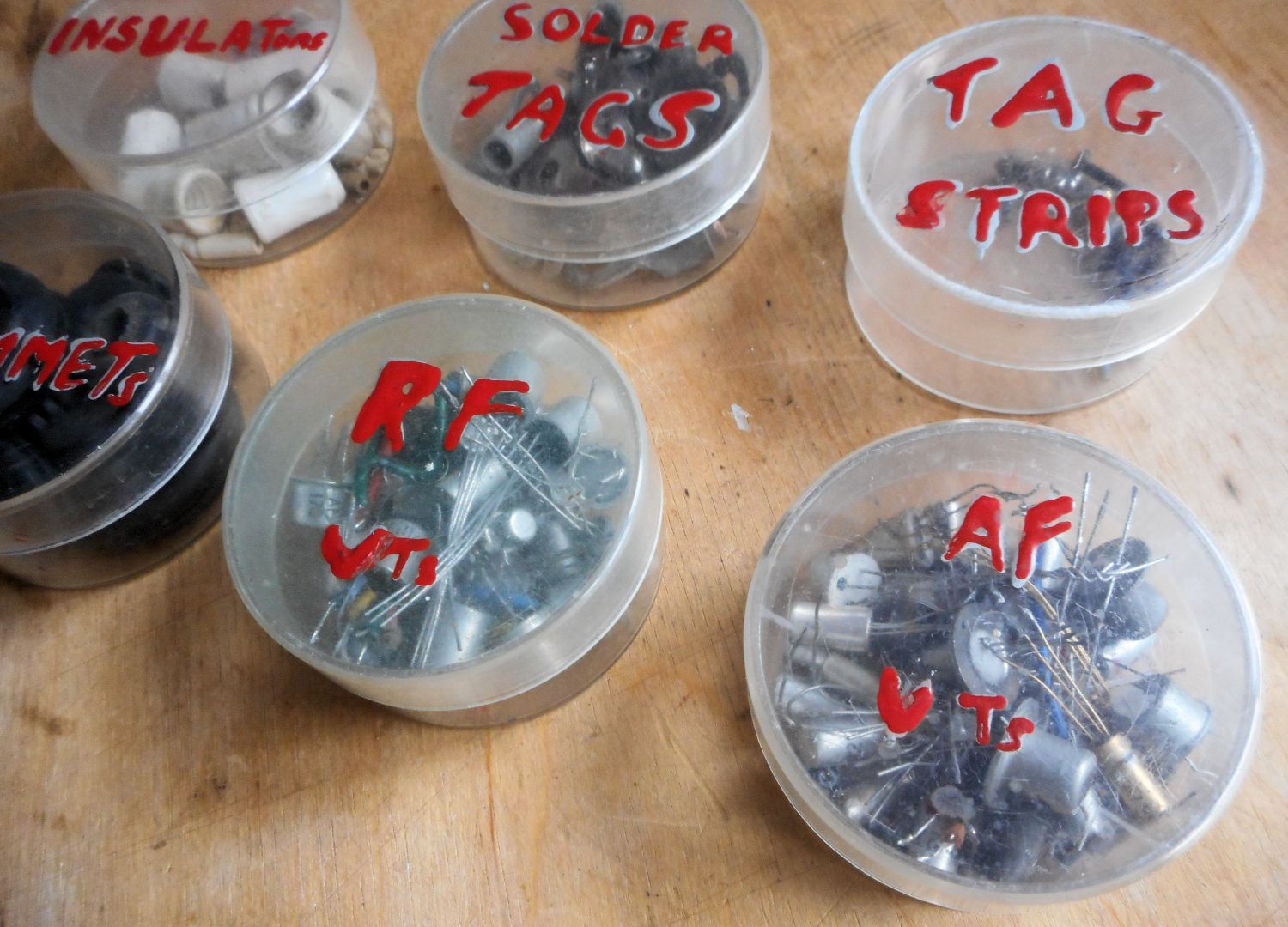
VT was the schematic designator for transistor - EMP blew those in plastic containers In attempting repairs I found that even new transistors not in use and half a metre away in plastic containers had been destroyed by electromagnetic induction. The only survivors were a few used transistors with their 25mm or so leads cut short. Transistors at that time were germanium PNP and came with long leads to suit mounting on tag boards as well as circuit boards. In subsequent decades the issue of semiconductors, electromagnetic pulse (EMP) and atomic weapons designed to maximise the effect, became a cause of concern. 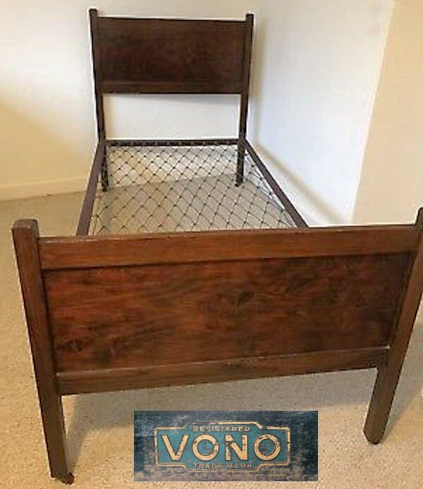
Metal Vono bedstead forming a partial Faraday screen? I was not aware of receiving any electrical shock but being awoken by the bang could well have masked that! Might lying asleep on a mattress 10cm above the metal mesh of the Vono bed mean its ground plane effect acted as some sort of partial Faraday screen providing protection from induced current and fatal shock? My sister still dislikes storms: "I woke in the night, it was dark, all the lights were off, the power was gone. All I felt was that I had heard a loud crack but what struck me most distinctly was an acrid, metallic smell drifting through the house. A bit like smoke but not really. Thunder and lightning raged outside, I was scared. As I ventured out of my room I realised something had happened in my brother’s room. I seem to remember a black mark on the wall above his bed." The house was on an 8 metre rise in ground level coming from the prevailing wind direction of south west, possibly making that location slightly more vulnerable. Luckily, my parents took a rational view of the chance of being struck again and had no objection to me installing a replacement aerial in the same place, though I did reposition the bed. For ever after there remained a charred black line all along the side of that bedspread. Radio Jackie's final confiscated transmitter Mains and modulation traansformers were the most awkward and expensive items for an AM transmittter, so in 1979 I devised this transformerless 500 Watt design using TV components and built on an A4-sized printed circuit board. The device was named De Amazin MF Rig, following the style of satirical comment on the Ugandan dictator Idi Amin, topical at the time. Live chassis radios were dying out but the technique was standard practice for TVs. This transmitter could run using screen grid modulation with negative feedback and no transformers at all or at higher power using a modulated EHT supply. 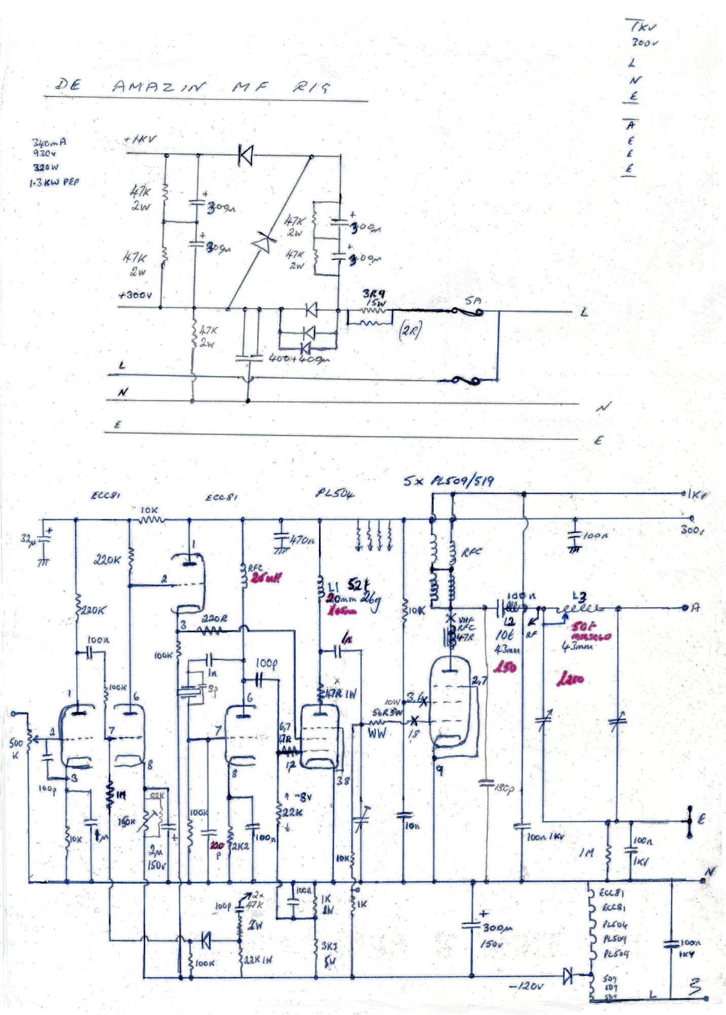
De Amazin MF Rig transmitter circuit diagram Together with a 300 Volt HT line, the PA's EHT line of 1kV was generated by a voltage tripler using standard TV electrolytic capacitors. The valves chosen all had 0.3 Amp heaters intended for series connection. In this case, the heaters themselves added up to mains voltage, meaning there was no need for the usual series dropper resistor. A tap point in the chain of heaters conveniently provided the 120 Volt negative bias supply. 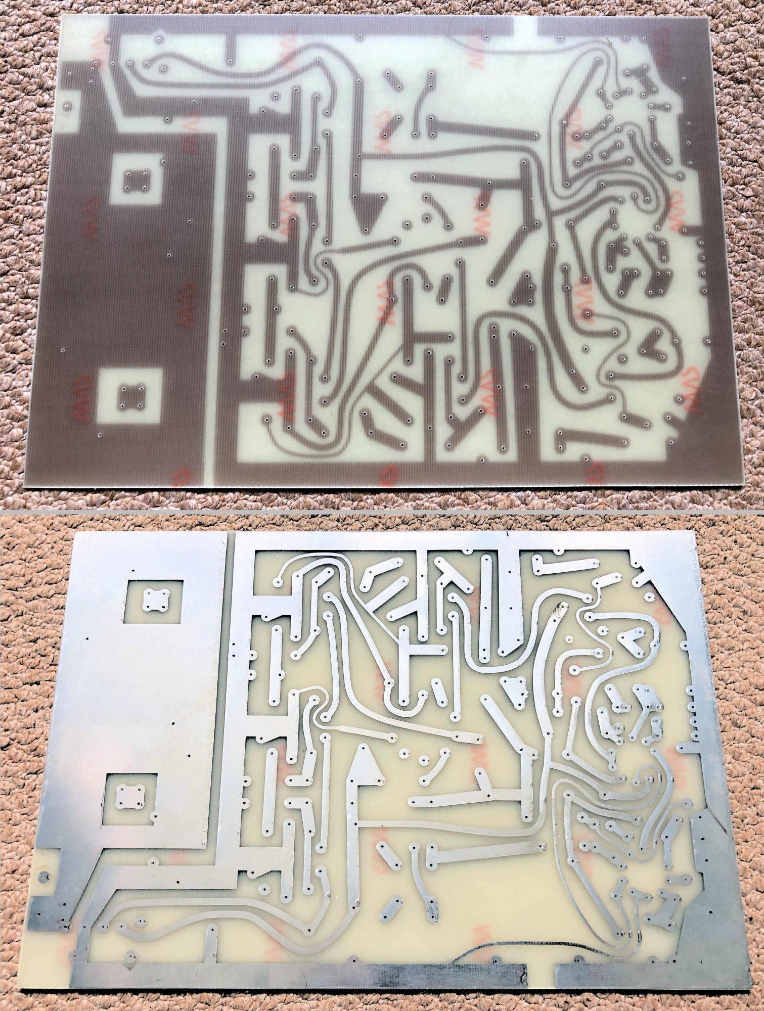
The A4-sized printed circuit board of De Amazin MF Rig The output stage used five parallel PL509/PL519 colour TV cathode ray tube line output pentodes in class C, feeding a two stage pi network transforming down to 50 Ohms, with blocking capacitors to deal with the live chassis. RF drive came from a frame output PL504 pentode, itself fed by half an ECC81 as a crystal oscillator. 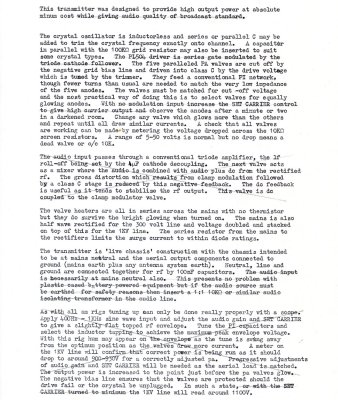
Circuit description - for anode modulation ignore crossed out parts The other half of the ECC81, together with an audio input ECC81, also fed with negative feedback DC and audio from rectified RF output, applied screen grid modulation to the PL504 driver. Careful adjustment could generate 300 Watts carrier of fully modulated RF output. 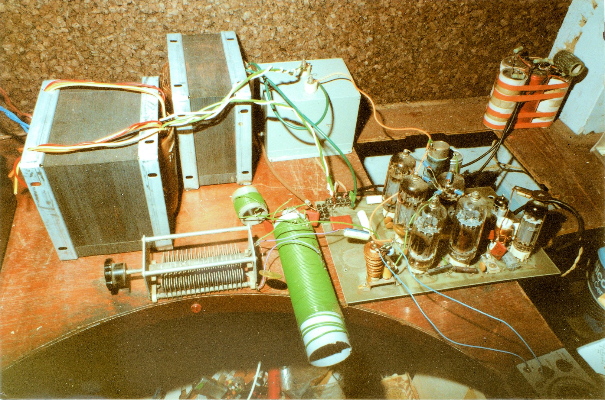
Choke and mod transformer, live chassis transmitter and voltage tripler Anode modulation was more straightforward and would produce even more power. Using a large audio transformer of the correct ratio but no air gap, a paper blocking capacitor with an LF choke to pass the DC and a solid state discotheque amplifier, a TR1000 from local Tooting company TUAC, the transmitter consumed 738 Watts and produced 545 Watts of RF output. Bundled in the corner are the electrolytics and voltage tripler. 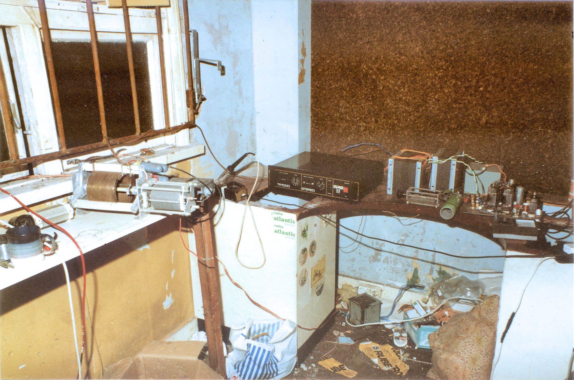
Aerial match, TUAC amplifier, modulation transformer and De Amazin MF Rig The aerial current meter showed a new high of 7 Amps, on the multi-wire figure seven aerial coming through the window, along with its earth mat, to the variometers and capacitors of the aerial matching network taking it to 50 Ohms. 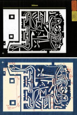
De Amazin master PC artwork, component layout and drilling diagram After 16 years of unlicensed broadcasting, this was the transmitter, complete with its 1332kHz crystal, confiscated from Radio Jackie during the final mean-minded raid at Abbotts Road, North Cheam, just ten minutes before the announced closedown at 7PM on Monday 4th February 1985. 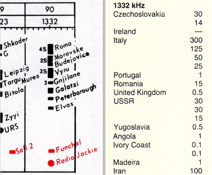
Nightime 1332kHz competition: EBU 1984 and WRTH 1985 WRTH: MIKE BARRACLOUGH Instead of struggling to hear our signal through nightime foreign interference at home, out in the Surrey Hills, that very night I happened to have tickets at the National Theatre on the South Bank. We dropped our kids off with their grandparents in Dorking for overnight babysitting and then drove through Jackie's main service area and on to central London, going happily into the theatre... since we'd parked and left the car before that infamous raid. Lead weights - useful things I made 1930s mains cable in houses used tinned copper conductors covered in vulcanised India rubber (VIR) and all sheathed in lead. The flammable rubber gradually degraded dangerously and crumbled, particularly where air surrounded exposed insulation at the ends, so old cabling was removed and replaced with PVC types. 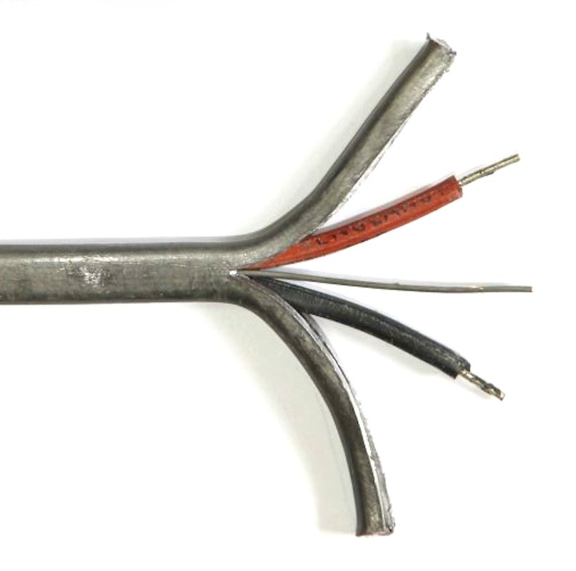
Lead sheathed VIR insulated mains wiring In the era before recycling, it seemed a bad idea just to throw away the old cables so I stripped the lead away from the wires inside and, using the kitchen scales, made up a pile weighing one pound (454gm). I put the lead scraps into an old tin can. In those days cans had paper labels which could be removed easily. 
A tin can containing lead scraps ready for heating As a teenager and while nobody was home, I put the tin onto one of the gas burners on the hob and heated it gently. With the delightful smell of burning dust and rubber, the lead duly melted. When it had cooled and solidified I cut and peeled off the steel tin can, releasing a useful lead weight. 
The four resulting lead weights. The can strengthening ridges show clearly The success of the first led to making three more similar weights which can be used in various combinations up to 4lb (1.8kg). 
Gluing the snapped slat on a garden bench The set of weights still find themselves used every month or so, often for flattening archive documents or holding down items whilst they are being glued. The best fix for crackling volume control pots: Rentokil Scratchy variable potentiometers have been the bane of audio equipment since the earliest days. Should there also be any DC flowing, perhaps from an ageing and leaking capacitor, the crackling can be really loud, driving the audio output stage into clipping as the volume control is turned. 
Bill Buskell's radio and TV shop in Covey Island, Mount Pleasant, Effingham As a young lad wanting electronic components I would cycle the one mile from home to motorbike enthusiast Bill Buskell's (William Francis Buskell, 1931 - 2014) radio and TV repair shop at the other side of the village. 
The carbon track and wiper inside a volume control The development of more expensive resistive cermet tracks largely solved the ageing problem in professional equipment but pots with carbon composition resistance elements still proliferate in consumer products and electric guitars. 
Wood preservative advertisements - Rentokil Kills Woodworm Crackling volume controls in TVs and radios were a frequent problem and Bill Buskell told me the best cure was to squirt Rentokil inside the pot. 
A switched dual gang potentiometer Contact cleaners, like Electrolube, or isopropyl alcohol would help for a short period but Rentokil made for a permanent repair. 
Nagra III - the staple for film and TV sound recordists Before cermet tracks existed, even multi-thousand dollar Nagra recorders, almost universal in film and TV production, developed scratchy pots which would instantly require the retake of a scene. 
The rather inaccessible pots inside the Nagra III Happily, treatment with Rentokil proved a permanent cure to crackling pots in Nagras. 
1970s visit to Stefan Kudelski and his Nagra factory, Paudex Vaud, Switzerland Apart from state of the art wow and flutter performance, Stefan Kudelski's Nagra recorders achieved remarkable dynamic range by pre-distorting their record audio to counteract saturation in the magnetic tape's ferric oxide. 
Bill Buskell trial-riding his Francis-Barnett 150cc in 1997 PHOTO: MARY WYLDE Was it more than coincidence that Rentokil were based at School Lane, Fetcham, which Bill Buskell drove past each day from his home in River Lane? I suspect he just randomly tried the solution on a scratchy pot and discovered how effective it was, so only those who knew him heard of the idea. 
Woodworm treatment from Rentokil with headquarters in Fetcham: It's unclear how the fluid works. Perhaps the oily residue which remains swells the carbon element, helping maintain contact with the wiper which is also coated. 
Rentokil woodworm fluid - 1960s and 2020s styles Original Rentokil had a strong aroma but, when my 1970s tin of Rentokil ran out, I found the modern 'low odour' version seems to work equally well. The fluid itself is not particularly conductive, sticking multimeter test probes into it 1cm apart measures around 50kOhms. I have no idea whether other brands of woodworm treatment work. 
Servicing tip columns in Radio Constructor and Practical Television Using Rentokil woodworm treatment on scratchy pots has not appeared in print. There was never a mention by the monthly service trade columns: Radio Contructor's In Your Workshop, featuring Smithy and his hapless sidekick Dick, or Servicing Television Receivers by Les Lawry-Johns in Practical Television. Discovering all independent FM stations were overdeviating As Britain gradually increased usage of the FM band, controlling the deviation of transmitters to minimise interference to adjacent channels, rather than simply avoiding distortion for listeners, became necessary. We developed a Peak Deviation Meter which could measure brief periods of overdeviation and many broadcasters worldwide acquired units. At Broadcast Warehouse in Croydon Roger Howe (1964 - 2020) always had one switched on above his design workbench. 
The Peak Deviation Meter dial, artwork done with Letraset and a Rotring pen Almost all BBC stations were peaking, correctly, at a deviation of ±75kHz. Pirates, of course, were all over the place but every one of the IBA stations was overdeviating, even going as high as ±120kHz. 
The 19 original ILR stations which were overdeviating in 1977 The IBA had proudly installed high quality Drawmer DL221 stereo limiters at their transmitter sites, quite failing to grasp that nice studio limiters are inherently unsuitable for transmission use. 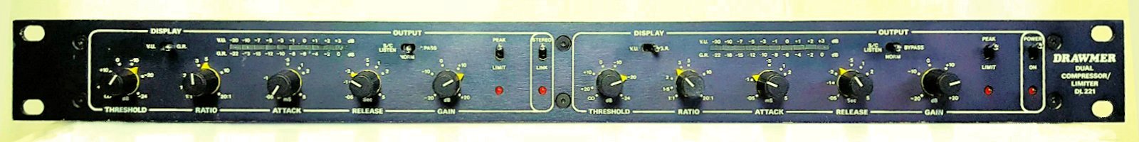
Drawmer stereo limiters - given the wrong job to do When a high audio level comes along the Drawmer responds by reducing the gain over a millisecond. This is pleasant subjectively but leaves the output level overshooting for that period. 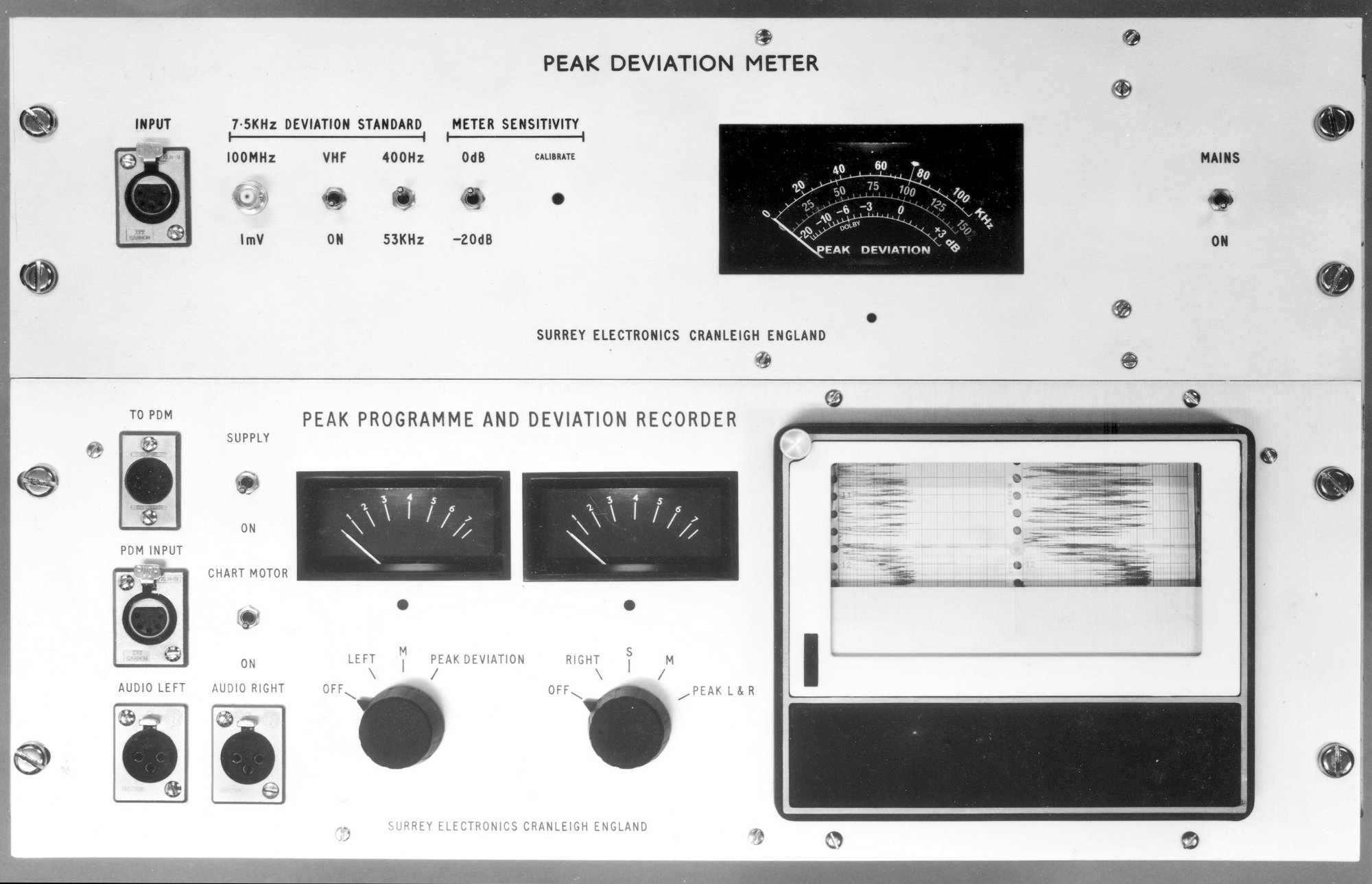
The Peak Deviation Meter and Chart Recorder Another product we developed was a peak-capturing chart recorder, with moving styli pressing down on pressure sensitive sprocketed paper to produce black traces. In the days before digital waterfall displays this was the first time such images had been seen. With independent transmission providers prohibited and no Ofcom in 1977, the BBC and IBA more or less regulated themselves within their own sub-bands. Initially, the IBA were rather inclined to dismiss these alarming charts as unimportant. 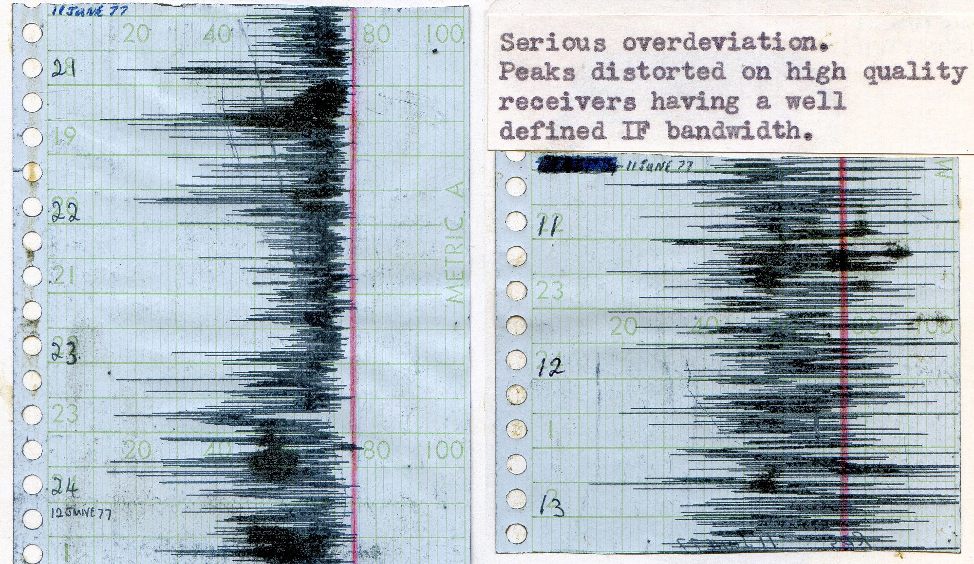
June 1977: BBC deviation up to 75kHz while IBA stations go beyond 100kHz Overshoots deviate the station's carrier outside its own 200kHz wide channel (or, more precisely, 203kHz wide for 99% of energy), potentially interfering with adjacent services. On tune, traditional receivers didn't mind much but the advent of crystal IF filters, with sharp cut off at the channel edges, meant receivers would lose signal whenever the carrier overdeviated, producing a novel kind of unpleasant distortion - momentary bursts of the white noise you hear when tuned to a vacant channel. At the rear of his home in Finchley, along with two assistants, Angus McKenzie MBE, G3OSS, (1933 - 2005) ran an audio and RF product testing laboratory and had become a respected reviewer. He also had a monthly 'FM Radio' column in HiFi News magazine. 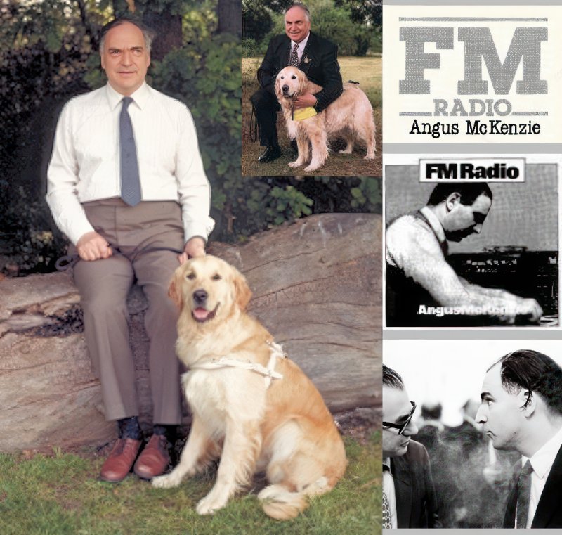
Angus McKenzie with his guide dog Simon PHOTO: KIRSTY MCKENZIE Angus knew of my measurements and, rather outraged, publicly wrote up the findings in HiFi News, thus creating considerable kerfuffle at the IBA headquarters in Crawley Court. The outcome was... installation of proper broadcast limiters at all ILR sites.
|
- - These tales are also available for organisations as an illustrated talk - -